I tried out the ParallelRouteLink source (Parallel Route Links) that is provided but it does not fit our needs completely.
We need orthogonal parallel links but I am not sure how to enable that.
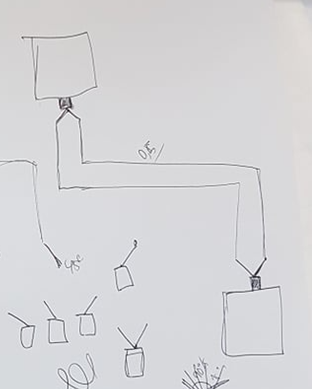
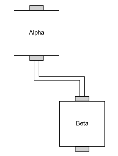
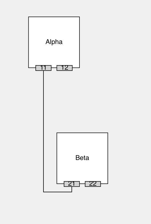
Here is an example how it should look ideally.
I tried out the ParallelRouteLink source (Parallel Route Links) that is provided but it does not fit our needs completely.
We need orthogonal parallel links but I am not sure how to enable that.
Here is an example how it should look ideally.
Well, it’s not the same, but maybe something like:
<!DOCTYPE html>
<html>
<head>
  <title>Minimal GoJS Sample</title>
  <!-- Copyright 1998-2022 by Northwoods Software Corporation. -->
</head>
<body>
  <div id="myDiagramDiv" style="border: solid 1px black; width:100%; height:600px"></div>

  <script src="https://unpkg.com/gojs"></script>
  <script id="code">
const $ = go.GraphObject.make;

const myDiagram =
  $(go.Diagram, "myDiagramDiv",
    {
      "undoManager.isEnabled": true
    });

myDiagram.nodeTemplate =
  $(go.Node, "Spot",
    { locationSpot: go.Spot.Center },
    new go.Binding("location", "loc", go.Point.parse).makeTwoWay(go.Point.stringify),
    $(go.Panel, "Auto",
      { width: 100, height: 100 },
      $(go.Shape, { fill: "white" }),
      $(go.TextBlock, { margin: 8, editable: true },
        new go.Binding("text").makeTwoWay())
    ),
    $(go.Shape,
      {
        alignment: go.Spot.Top, alignmentFocus: go.Spot.Bottom,
        width: 30, height: 10, fill: "lightgray",
        portId: "in", cursor: "pointer",
        toLinkable: true,
        toSpot: go.Spot.TopSide
      }),
    $(go.Shape,
      {
        alignment: go.Spot.Bottom, alignmentFocus: go.Spot.Top,
        width: 30, height: 10, fill: "lightgray",
        portId: "out", cursor: "pointer",
        fromLinkable: true,
        fromSpot: go.Spot.BottomSide
      }),
  );

myDiagram.linkTemplate =
  $(go.Link,
    { routing: go.Link.Orthogonal, fromPortId: "out", toPortId: "in" },
    $(go.Shape)
  );

myDiagram.model = new go.GraphLinksModel(
  [
    { key: 1, text: "Alpha", loc: "0 0" },
    { key: 2, text: "Beta", loc: "100 200" },
  ],
  [
    { from: 1, to: 2 },
    { from: 1, to: 2 }
  ]);
  </script>
</body>
</html>
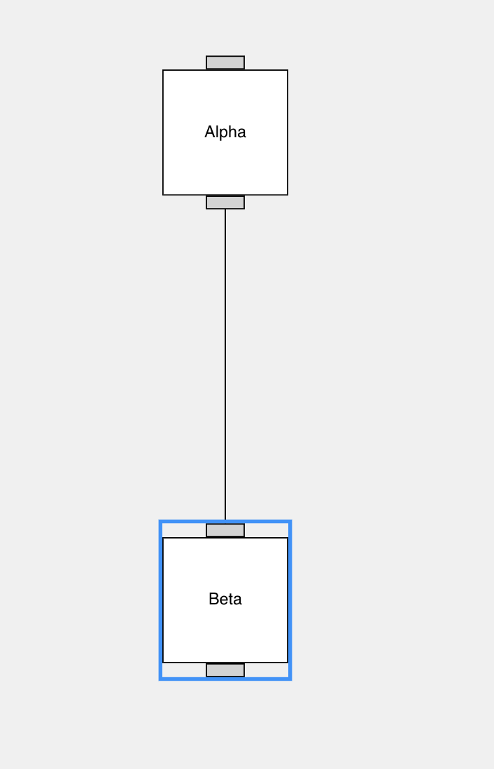
This produces:
You could even change the appearance of each port to use a custom geometry instead of a simple rectangle.
What numbers of links will there be between any pair of ports? What about numbers at any port?
hey walter! thank you for your quick reply. that would be a good solution for our case too, however, whenever I add a Layout like in our case the LayeredDigraphLayout the links get merged into one. is there a way to prevent that?
here is the Layout we are using:
        layout: $(FlatLayeredDigraphLayout, {
            direction: 90,
            layerSpacing: 230,
            linkSpacing: 40, // Undocumented prop https://forum.nwoods.com/t/how-to-control-spacing-between-vertical-line-link/5462
        }),
FlatLayeredDigraphLayout:
const SPACING_BETWEEN_BOTTOM_NODES = 50;
/**
 * This is a copied and slightly tweaked layout from this source:
 * https://gojs.net/latest/samples/parseTree.html
 * Instead of a TreeLayout it is extending the LayeredDigraphLayout
 */
export class FlatLayeredDigraphLayout extends go.LayeredDigraphLayout {
    // This assumes the TreeLayout.angle is 90 -- growing downward
    commitLayout() {
        super.commitLayout(); // call base method first
        // find maximum Y position of all Nodes
        // eslint-disable-next-line no-restricted-syntax
        let y = -Infinity;
        const vertexes =
            this.network?.vertexes.filter(v => Boolean(v.node)) ||
            new go.Set<go.LayoutVertex>();
        vertexes.each(v => {
            y = Math.max(y, v.node!.position.y || 0);
        });
        // move down all leaf nodes to that Y position, and align next to each other by setting X position
        const bottomVertexes = vertexes
            .toArray()
            .filter(vertex => vertex.destinationEdges.count === 0);
        // eslint-disable-next-line no-restricted-syntax
        let widthOfPreviousItems = 0;
        bottomVertexes.forEach((v: go.LayoutVertex) => {
            // shift the node down to Y and to calculated X position so nodes don't overlap
            // eslint-disable-next-line no-param-reassign
            v.node!.position = new go.Point(widthOfPreviousItems, y);
            // extend the last segment vertically
            // eslint-disable-next-line no-param-reassign
            v.node!.toEndSegmentLength = Math.abs(v.centerY - y);
            // sum width of all bottom nodes before and adding spacing
            widthOfPreviousItems += v.width + SPACING_BETWEEN_BOTTOM_NODES;
        });
    }
}
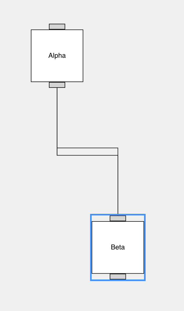
and the output in the diagram:
That’s because some layouts automatically make sure that the links are going in the general direction that the layout wants. For this case, you can set LayeredDigraphLayout.setsPortSpots to false. That way the Link.fromSpot and Link.toSpot values aren’t set by the layout and the port’s GraphObject.fromSpot and toSpot values apply as default values for the routing of the links connected with those ports.
that is already very helpful! I got it working without ports, but I struggle now having those orthogonal parallel Links for variable ports. how can I achieve it there?
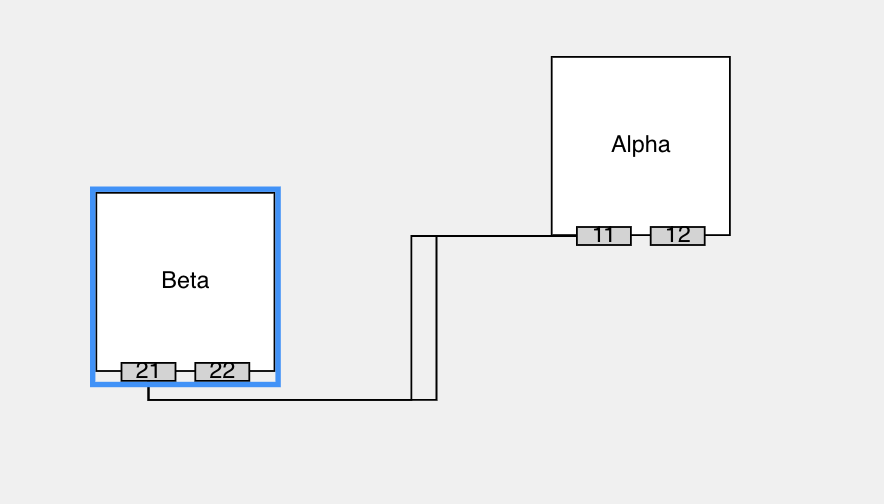
here is the example, you can see that both links are again merged into one link:
here is the code:
the diagram model and templates:
 const diagram = go.GraphObject.make(go.Diagram, {
        'clickCreatingTool.archetypeNodeData': {
            text: 'new node',
            color: 'lightblue',
        },
        layout: $(FlatLayeredDigraphLayout, {
            setsPortSpots: false,
            direction: 90,
            layerSpacing: 230,
            linkSpacing: 40, // Undocumented prop https://forum.nwoods.com/t/how-to-control-spacing-between-vertical-line-link/5462
        }),
        model: $(go.GraphLinksModel, {
            nodeKeyProperty: 'key',
            linkKeyProperty: 'id',
            linkFromPortIdProperty: 'fromPort',
            linkToPortIdProperty: 'toPort',
            nodeCategoryProperty: 'category',
        }),
        padding: new go.Margin(100, 50, 40, 50),
    });

    diagram.nodeTemplate = $(
        go.Node,
        'Spot',
        { locationSpot: go.Spot.Center },
        $(
            go.Panel,
            'Auto',
            { width: 100, height: 100 },
            $(go.Shape, { fill: 'white' }),
            $(
                go.TextBlock,
                { margin: 8, editable: true },
                new go.Binding('text').makeTwoWay()
            )
        ),
        $(
            go.Panel,
            'Horizontal',
            { alignment: go.Spot.Bottom },
            new go.Binding('itemArray', 'ports'),
            {
                itemTemplate: $(
                    go.Panel,
                    'Auto',
                    { margin: new go.Margin(0, 5, 0, 5) },
                    $(go.Shape, new go.Binding('portId', 'id'), {
                        alignment: go.Spot.Top,
                        alignmentFocus: go.Spot.Bottom,
                        width: 30,
                        height: 10,
                        fill: 'lightgray',
                        cursor: 'pointer',
                        toLinkable: true,
                        toSpot: go.Spot.Bottom,
                    }),
                    $(
                        go.TextBlock,
                        { margin: 8, editable: true },
                        new go.Binding('text', 'id').makeTwoWay()
                    )
                ),
            }
        )
    );

    diagram.linkTemplate = $(
        go.Link,
        {
            routing: go.Link.Orthogonal,
        },
        $(go.Shape)
    );
and the data:
        const nodes = [
            {
                key: 1,
                text: 'Alpha',
                ports: [{ id: '11' }, { id: '12' }],
                loc: '0 0',
            },
            {
                key: 2,
                text: 'Beta',
                ports: [{ id: '21' }, { id: '22' }],
                loc: '100 200',
            },
        ];
        const links = [
            { id: 5, from: 1, to: 2, fromPort: '11', toPort: '21' },
            { id: 6, from: 1, to: 2, fromPort: '11', toPort: '21' },
        ];
You’ve set toSpot to go.Spot.Bottom rather than to go.Spot.BottomSide. You have to use the “…Side” Spots if you want automatic spreading of links at a port. That’s what I used in the code I posted above.
Still, the routing isn’t that smart when there are multiple ports on one side of a node and there are multiple links connected. However, there is code in the Dynamic Ports sample that helps: Dynamic Ports (That code is independent of whether the number of ports changes dynamically.)
ah okay, thanks for the clarification. and is there a way to again show the links as separate lines going from port to port?
here are the templates:
diagram.nodeTemplate = $(
        go.Node,
        'Spot',
        { locationSpot: go.Spot.Center },
        $(
            go.Panel,
            'Auto',
            { width: 100, height: 100 },
            $(go.Shape, { fill: 'white' }),
            $(
                go.TextBlock,
                { margin: 8, editable: true },
                new go.Binding('text').makeTwoWay()
            )
        ),
        $(
            go.Panel,
            'Horizontal',
            { alignment: go.Spot.Top },
            new go.Binding('itemArray', 'portsTop'),
            {
                itemTemplate: $(
                    go.Panel,
                    'Auto',
                    { margin: new go.Margin(0, 5, 0, 5) },
                    $(go.Shape, new go.Binding('portId', 'id'), {
                        alignment: go.Spot.Top,
                        alignmentFocus: go.Spot.Bottom,
                        width: 30,
                        height: 10,
                        fill: 'lightgray',
                        cursor: 'pointer',
                        toLinkable: true,
                        toSpot: go.Spot.TopSide,
                    }),
                    $(
                        go.TextBlock,
                        { margin: 8, editable: true },
                        new go.Binding('text', 'id').makeTwoWay()
                    )
                ),
            }
        ),
        $(
            go.Panel,
            'Horizontal',
            { alignment: go.Spot.Bottom },
            new go.Binding('itemArray', 'portsBottom'),
            {
                itemTemplate: $(
                    go.Panel,
                    'Auto',
                    { margin: new go.Margin(0, 5, 0, 5) },
                    $(go.Shape, new go.Binding('portId', 'id'), {
                        alignment: go.Spot.Top,
                        alignmentFocus: go.Spot.Bottom,
                        width: 30,
                        height: 10,
                        fill: 'lightgray',
                        cursor: 'pointer',
                        toLinkable: true,
                        toSpot: go.Spot.BottomSide,
                    }),
                    $(
                        go.TextBlock,
                        { margin: 8, editable: true },
                        new go.Binding('text', 'id').makeTwoWay()
                    )
                ),
            }
        )
    );

    diagram.linkTemplate = $(
        go.Link,
        {
            routing: go.Link.Orthogonal,
        },
        $(go.Shape)
    );
and the data:
        const nodes = [
            {
                key: 1,
                text: 'Alpha',
                portsBottom: [{ id: '11' }, { id: '12' }],
                loc: '0 0',
            },
            {
                key: 2,
                text: 'Beta',
                portsTop: [{ id: '21' }, { id: '22' }],
                loc: '100 200',
            },
        ];
        const links = [
            { id: 5, from: 1, to: 2, fromPort: '11', toPort: '21' },
            { id: 6, from: 1, to: 2, fromPort: '11', toPort: '21' },
        ];
They are already spread out at “Beta”/21. I don’t know why they’re not spread out at “Alpha”/11. Did you set GraphLinksModel.linkFromPortIdProperty as well as linkToPortIdProperty before supplying those Arrays of data?
yes, this is my model definition. it is defined before the templates are set. I was also wondering if the order makes a difference here.
    const diagram = go.GraphObject.make(go.Diagram, {
        'clickCreatingTool.archetypeNodeData': {
            text: 'new node',
            color: 'lightblue',
        },
        layout: $(FlatLayeredDigraphLayout, {
            setsPortSpots: false,
            direction: 90,
            layerSpacing: 230,
            linkSpacing: 40, // Undocumented prop https://forum.nwoods.com/t/how-to-control-spacing-between-vertical-line-link/5462
        }),
        model: $(go.GraphLinksModel, {
            nodeKeyProperty: 'key',
            linkKeyProperty: 'id',
            linkFromPortIdProperty: 'fromPort',
            linkToPortIdProperty: 'toPort',
            nodeCategoryProperty: 'category',
        }),
        padding: new go.Margin(100, 50, 40, 50),
    });
Ah, a common mistake: it would have helped if you had set the correct property:
fromSpot: go.Spot.BottomSide,
instead of setting the toSpot again.
so if we do fromSpot: go.Spot.BottomSide, I’m getting some gaps between the parallel links like the below pic, any way to reduce the gap?
Sorry we missed this. If you don’t want the gaps, you may want to just use go.Spot.Bottom instead.
Which gaps are you trying to remove?
What @jhardy suggests will remove the vertical gaps between the vertical line segments.
If you want to remove the horizontal gaps between the horizontal line segments, set LayeredDigraphLayout.linkSpacing to zero.