Auto Arrange of diagram

As per our requirement -

  1. User can add multiple nodes and link them .
  2. On clicking auto arrange button my diagram should get auto arranged automatically.

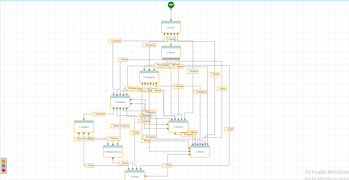
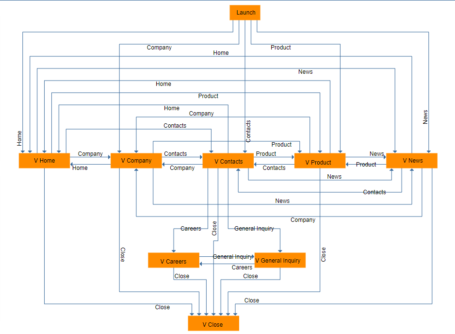
Our Requirement (Example from some other library)

Before Auto Arrange

After Auto Arrange

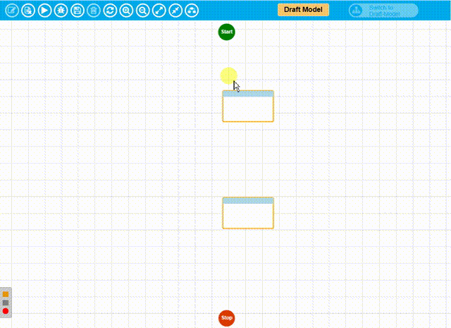
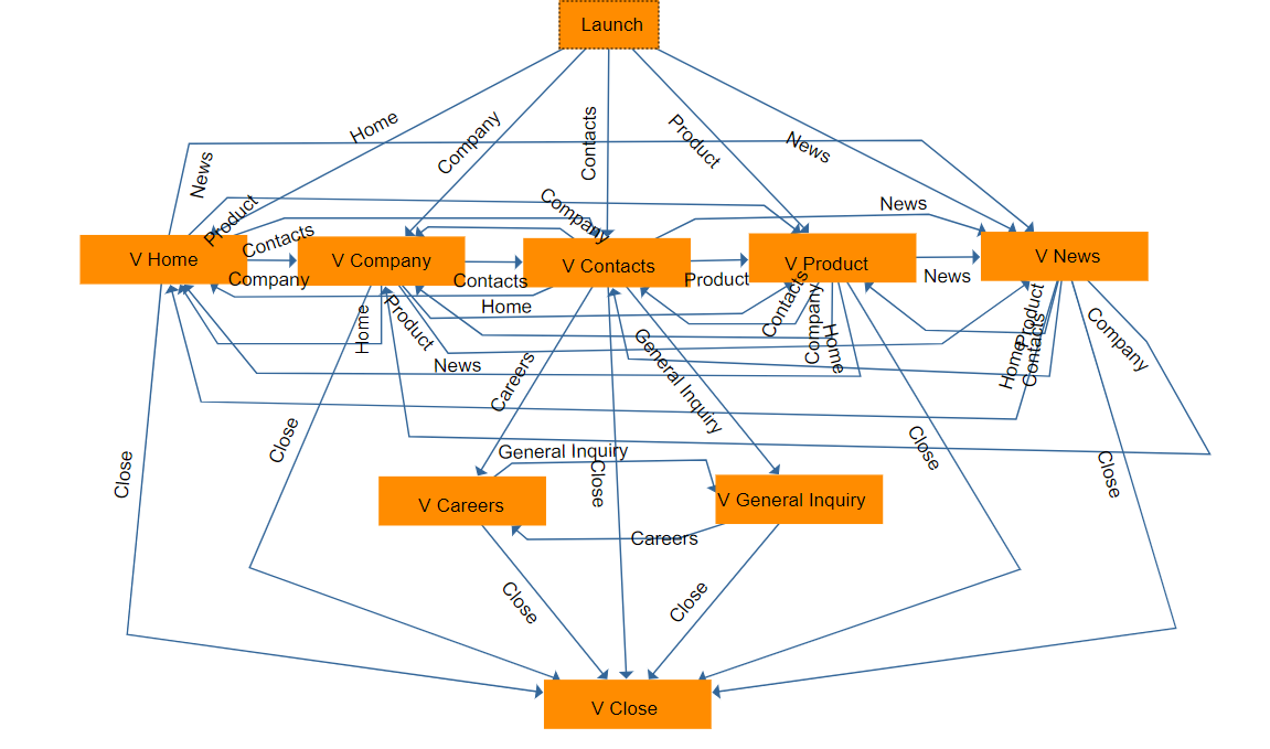
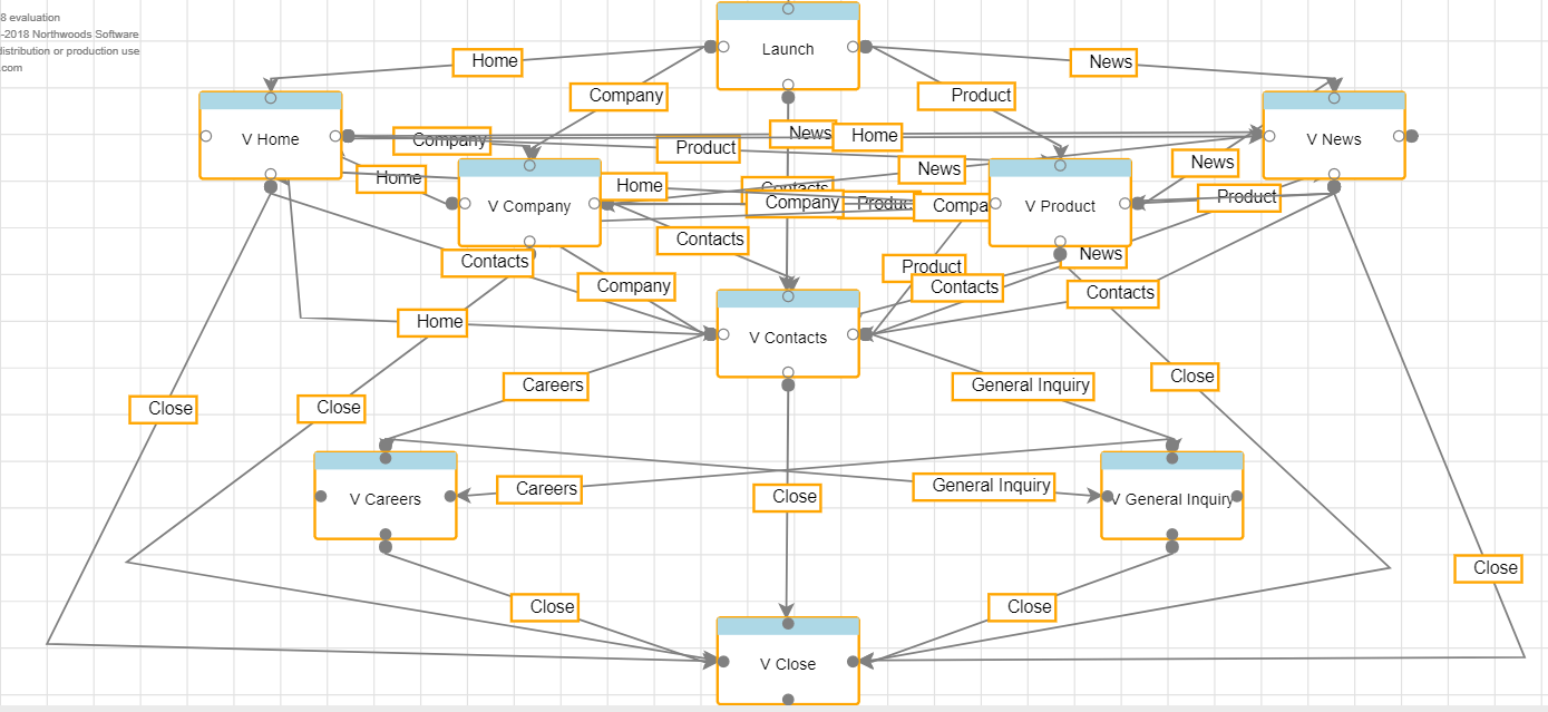
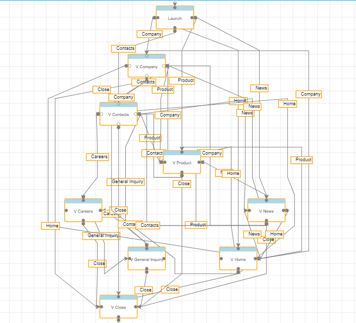
While working on GoJS

Before Auto Arrange

After Auto Arrange

What we have tried so far

  1. Editor (Code)
    // Licensed version

myDiagram = $(go.Diagram, “diagram_MBT_Graph”, // must name or refer to the DIV HTML element
{
initialContentAlignment: go.Spot.Center,
draggingTool: new GuidedDraggingTool(), // defined in GuidedDraggingTool.js
“draggingTool.horizontalGuidelineColor”: “blue”,
“draggingTool.verticalGuidelineColor”: “blue”,
“draggingTool.centerGuidelineColor”: “green”,
“draggingTool.guidelineWidth”: 1,
“draggingTool.isCopyEnabled”: false,
“animationManager.isEnabled”: false,
“linkingTool.direction”: go.LinkingTool.ForwardsOnly,
allowDrop: true, // must be true to accept drops from the Palette
“LinkDrawn”: showLinkLabel, // this DiagramEvent listener is defined below
“LinkRelinked”: showLinkLabel,
scrollsPageOnFocus: false,
“undoManager.isEnabled”: true,
allowHorizontalScroll: true,
allowVerticalScroll: true,
}
});

myDiagram.nodeTemplate =
$(go.Node, “Auto”,

    { layoutConditions: go.Part.LayoutAdded | go.Part.LayoutRemoved, zOrder: 2 },
        //{ locationSpot: go.Spot.Center, resizable: false, fromSpot: go.Spot.AllSides, toSpot: go.Spot.AllSides, minSize: new go.Size(108, 67) },
         new go.Binding("location", "loc", go.Point.parse).makeTwoWay(go.Point.stringify),
         { resizable: false, resizeObjectName: "PANEL", resizeAdornmentTemplate: nodeResizeAdornmentTemplate, desiredSize: new go.Size(108, 67), minSize: new go.Size(108, 67), maxSize: new go.Size(220, 120) },
         new go.Binding("angle").makeTwoWay(),
         new go.Binding("position", "position", go.Point.parse).makeTwoWay(go.Point.stringify),
         new go.Binding("desiredSize", "size", go.Size.parse).makeTwoWay(go.Size.stringify),
        $(go.Shape, "RoundedRectangle",
          {
              parameter1: 2,
              fill: fill, stroke: "orange", strokeWidth: 2,
              spot1: new go.Spot(0, 0, 1, 1),
              spot2: new go.Spot(1, 1, -1, 0),
              minSize: new go.Size(95, 59),
              maxSize: new go.Size(220, 120),
          },
            new go.Binding("figure", "figure").makeTwoWay(),
            new go.Binding("fill", "fill").makeTwoWay(),
            new go.Binding("stroke", "stroke").makeTwoWay()
          ),
        $(go.Panel, "Vertical",
          { alignment: go.Spot.Top, stretch: go.GraphObject.Horizontal, minSize: new go.Size(108, 67) },
          $(go.Panel, "Table",
            { background: "lightblue", stretch: go.GraphObject.Horizontal, width: 15.5, height: 13 },
            //$("TreeExpanderButton", { alignment: go.Spot.Left }),
            //$("Button", { alignment: go.Spot.Right, width: 13.5, height: 13.5, visible: false })
                $(go.Shape, "StopSign", {
                    alignment: go.Spot.TopLeft, margin: 2,
                    fill: "red", width: 8, height: 8, stroke: null,
                    visible: visible
                }, new go.Binding("visible", "visible").makeTwoWay())),
          $(go.TextBlock,
          {
              font: "12px Arial, sans-serif", //stroke: lightText,
              margin: 4,
              stretch: go.GraphObject.Horizontal, textAlign: "center",
              height: 38,
              maxLines: 3,
              // cursor: "move",
              verticalAlignment: go.Spot.Center,
              editable: true, isMultiline: true, //textValidation: validateText,
              textEdited: function (textBlock, previousText, currentText) {
                  if (previousText != currentText) {
                      $scope.MBTOperationScope.renameNode(currentText.trim());
                  }
              },
          },
         new go.Binding("text", "text").makeTwoWay())),
          
          { contextMenu: $(go.Adornment) },
          makePort("T", go.Spot.Top, true, true),
          makePort("L", go.Spot.Left, true, true),
          makePort("R", go.Spot.Right, true, true),
          makePort("B", go.Spot.Bottom, true, true),

      );

function makePort(name, spot, output, input) {
return $(go.Shape, “Circle”,
{
fill: “gray”,//transparent
stroke: “gray”, // this is changed to “white” in the showPorts function
desiredSize: new go.Size(8, 8),
alignment: spot, alignmentFocus: spot, // align the port on the main Shape
portId: name, // declare this object to be a “port”
fromSpot: spot, toSpot: spot, // declare where links may connect at this port
fromLinkable: output, toLinkable: input, // declare whether the user may draw links to/from here
cursor: “pointer”, // show a different cursor to indicate potential link point
fromLinkableSelfNode: true, fromLinkableDuplicates: true, toLinkableSelfNode: true, toLinkableDuplicates: true,
});
}

    myDiagram.linkTemplate =
      $(go.Link,
        {
            relinkableFrom: true,
            relinkableTo: true,
            reshapable: true,
            resegmentable: true,
            fromLinkable: true,
            fromLinkableSelfNode: true,
            fromLinkableDuplicates: true,
            toLinkable: true,
            toLinkableSelfNode: true,
            toLinkableDuplicates: true,
            zOrder: 1,
            mouseEnter: function (e, link) {
                console.log('link focus in');
                dataFactory.customNodeObject['e'] = e;
                dataFactory.customNodeObject['link'] = link;
                link.findObject("HIGHLIGHT").stroke = "rgba(24,87,255,2.0)";
                link.isHighlighted = true;
            },
            mouseLeave: function (e, link) {
                console.log('link focus out');
                dataFactory.customNodeObject = new Object();
                link.findObject("HIGHLIGHT").stroke = "gray"; link.isHighlighted = false;
            },
            mouseDrop: CheckLockBeforeDragDropOnLink,
            toShortLength: 2,
        },
        new go.Binding("points").makeTwoWay(),
         new go.Binding("zOrder"),
        new go.Binding("routing", "routing"),
        new go.Binding("curviness"),
        $(go.Shape, { stroke: "gray", strokeWidth: 1.5, name: "HIGHLIGHT" }),
        $(go.Shape, { fromArrow: "Circle", fill: "gray", strokeWidth: 2, stroke: "gray" }),
        $(go.Shape, { toArrow: 'Standard', fill: "gray", strokeWidth: 2, stroke: "gray" }),
            $(go.Panel, "Auto",
         { _isLinkLabel: true, cursor: "move" },  // marks this Panel as being a draggable label
       $(go.Shape, { isPanelMain: true, fill: "white", stroke: "orange", strokeWidth: 2 },
             new go.Binding("stroke", "stroke", function (t) {
                 debugger
                 return t.trim() !== ''
             }).makeTwoWay()
        ),
      $(go.Shape, "StopSign",
      {
          alignment: go.Spot.TopLeft, margin: 3,
          width: 8, height: 8, fill: "red", visible: visible, stroke: null
      },
     new go.Binding("visible", "visible").makeTwoWay()),
     new go.Binding('visible', 'text', function (t) { return t.trim() !== '' }),
     
    $(go.TextBlock, "Label", {
        margin: 3, editable: true,
        isMultiline: true,  // don't allow embedded newlines
        textValidation: validateText,
        segmentIndex: 0, segmentFraction: 0.5,
        textEdited: function (textBlock, previousText, currentText) {
            if (previousText != currentText) {
                var selectedData = myDiagram.selection.first().data;
                if (selectedData.hasOwnProperty('EdgeID')) {
                    var edgeName = currentText.split('\u00AD');
                    if (edgeName.length > 1) {
                        edgeName = currentText.split('\u00AD')[1].trim();
                    } else {
                        edgeName = currentText.trim();
                    }
                    $scope.MBTOperationScope.renameEdge(edgeName);
                }
            }
        }
    },
        new go.Binding('visible', 'text', function (t) {
            return t.trim() !== ''
        }),
            new go.Binding("text", "text", function (e) {
                if (e != "") {
                    return "\u00AD   " + e;
                }
            }).makeTwoWay(),
     {
         toolTip:
                $("ToolTip",
                  new go.Binding("visible", "text", function (t) {
                      if (t.trim('') == "Associated FL Name :") {
                          t = '';
                      }
                      return !!t;
                  }).ofObject("TB"),
                  $(go.TextBlock,
                    { name: "TB", margin: 4, font: "bold 12px Verdana,serif", stroke: "black" },
                    new go.Binding("text", "", diagramNodeInfo))
                )
     }
           ),
            { contextMenu: $(go.Adornment) },
         new go.Binding("segmentIndex").makeTwoWay(),
         new go.Binding("segmentFraction").makeTwoWay()
       )
     );
    myDiagram.toolManager.linkingTool.temporaryLink.routing = go.Link.Orthogonal;

function SpotLinkingTool() {
debugger
go.LinkingTool.call(this);
}
go.Diagram.inherit(SpotLinkingTool, go.LinkingTool);

function MultiArrowLink() {
    go.Link.call(this);
   // this.routing = go.Link.Orthogonal;
}
go.Diagram.inherit(MultiArrowLink, go.Link);
// produce a Geometry from the Link's route
MultiArrowLink.prototype.makeGeometry = function () {
    debugger
    // get the Geometry created by the standard behavior
    var geo = go.Link.prototype.makeGeometry.call(this);
    if (geo.type !== go.Geometry.Path || geo.figures.length === 0) return geo;
    var mainfig = geo.figures.elt(0);  // assume there's just one PathFigure
    var mainsegs = mainfig.segments;
    var arrowLen = 8;  // length for each arrowhead
    var arrowWid = 3;  // actually half-width of each arrowhead
    var fx = mainfig.startX;
    var fy = mainfig.startY;
    for (var i = 0; i < mainsegs.length; i++) {
        var a = mainsegs.elt(i);
        // assume each arrowhead is a simple triangle
        var ax = a.endX;
        var ay = a.endY;
        var bx = ax;
        var by = ay;
        var cx = ax;
        var cy = ay;
        if (fx < ax - arrowLen) {
            bx -= arrowLen; by += arrowWid;
            cx -= arrowLen; cy -= arrowWid;
        } else if (fx > ax + arrowLen) {
            bx += arrowLen; by += arrowWid;
            cx += arrowLen; cy -= arrowWid;
        } else if (fy < ay - arrowLen) {
            bx -= arrowWid; by -= arrowLen;
            cx += arrowWid; cy -= arrowLen;
        } else if (fy > ay + arrowLen) {
            bx -= arrowWid; by += arrowLen;
            cx += arrowWid; cy += arrowLen;
        }
        geo.add(new go.PathFigure(ax, ay, true)
                .add(new go.PathSegment(go.PathSegment.Line, bx, by))
                .add(new go.PathSegment(go.PathSegment.Line, cx, cy).close()));
        fx = ax;
        fy = ay;
    }
    return geo;
};
  1. On Auto Arrange button click

myDiagram.layout =
$(go.LayeredDigraphLayout,
{
direction: 90,
isOngoing: true, // sets the postion of the node to current drag pos
layerSpacing: 50,
setsPortSpots: false,
columnSpacing: 40,
isRouting: true,
isValidLayout: true,
isViewportSized: true,
aggressiveOption: go.LayeredDigraphLayout.AggressiveMore,
cycleRemoveOption: go.LayeredDigraphLayout.CycleDepthFirst,
initializeOption: go.LayeredDigraphLayout.InitDepthFirstOut,
layeringOption: go.LayeredDigraphLayout.LayerOptimalLinkLength,
packOption: go.LayeredDigraphLayout.PackAll
});
myDiagram.layoutDiagram(true)
myDiagram.model = go.Model.fromJson(myDiagram.model.toJSON());

  1. Problems
    • links get hidden behind node
    • graph is no precise.

Is there a reason you have four ports on each node instead of using the default behavior where the one and only port is the border of the node? That way if you set fromSpot and toSpot to go.Spot.AllSides, you’ll get routing behavior more similar to what I suspect that you want.

I have provided 4 ports to make connection between nodes.If i remove all ports and setting fromSpot and toSpot to go.Spot.AllSides block me in creating links between nodes.

Though it solves the first problem (links get hidden behind node)

See Is it possible to auto arrange all the links present between two Nodes - #4 by Rishabh

Followed exactly what you told

$(go.Shape, “RoundedRectangle”,
{
parameter1: 2, portId: “”,
fill: fill, stroke: “orange”, strokeWidth: 2,
spot1: new go.Spot(0, 0, 1, 1),
spot2: new go.Spot(1, 1, -1, 0),
minSize: new go.Size(95, 59),
maxSize: new go.Size(220, 120), fromLinkable: true, fromLinkableSelfNode: true, fromLinkableDuplicates: true,
toLinkable: true, toLinkableSelfNode: true, toLinkableDuplicates: true
},

But now my view is not precise as before , links are get overlapped with nodes.

You haven’t set fromSpot and toSpot to be go.Spot.AllSides.

I have set fromSpot and toSpot to be go.Spot.AllSides.

$(go.Node, “Auto”,
{
fromSpot: go.Spot.AllSides, toSpot: go.Spot.AllSides
}, new go.Binding(“location”, “loc”, go.Point.parse).makeTwoWay(go.Point.stringify),
{ resizable: false, resizeObjectName: “PANEL”, resizeAdornmentTemplate: nodeResizeAdornmentTemplate, desiredSize: new go.Size(108, 67), minSize: new go.Size(108, 67), maxSize: new go.Size(220, 120) },
new go.Binding(“angle”).makeTwoWay(),
new go.Binding(“position”, “position”, go.Point.parse).makeTwoWay(go.Point.stringify),
new go.Binding(“desiredSize”, “size”, go.Size.parse).makeTwoWay(go.Size.stringify),
$(go.Shape, “RoundedRectangle”,
{
parameter1: 2, portId: “”,
fill: fill, stroke: “orange”, strokeWidth: 2,
spot1: new go.Spot(0, 0, 1, 1),
spot2: new go.Spot(1, 1, -1, 0),
minSize: new go.Size(95, 59),
maxSize: new go.Size(220, 120), fromLinkable: true, fromLinkableSelfNode: true, fromLinkableDuplicates: true,
toLinkable: true, toLinkableSelfNode: true, toLinkableDuplicates: true
},
new go.Binding(“figure”, “figure”).makeTwoWay(),
new go.Binding(“fill”, “fill”).makeTwoWay(),
new go.Binding(“stroke”, “stroke”).makeTwoWay()
),

But you had not set those properties on the port element.

All port properties need to go on the GraphObject that act as ports. That means when some object has GraphObject.portId set or bound to some string, that’s the object whose port properties need to be set.

If there is more than one port, one couldn’t set different port properties if they were all on the Node.

Walter , it will be very helpful if you give me an example.

$(go.Node, "Auto",
  {
    resizable: false, resizeObjectName: "PANEL",
    resizeAdornmentTemplate: nodeResizeAdornmentTemplate,
    desiredSize: new go.Size(108, 67),
    minSize: new go.Size(108, 67),
    maxSize: new go.Size(220, 120)
  },
  new go.Binding("angle").makeTwoWay(),
  new go.Binding("location", "loc", go.Point.parse).makeTwoWay(go.Point.stringify),
  new go.Binding("desiredSize", "size", go.Size.parse).makeTwoWay(go.Size.stringify),
  $(go.Shape, "RoundedRectangle",
    {
      parameter1: 2, portId: "",
      fromSpot: go.Spot.AllSides, toSpot: go.Spot.AllSides, // <------spots should be here
      fill: fill, stroke: "orange", strokeWidth: 2,
      spot1: new go.Spot(0, 0, 1, 1),
      spot2: new go.Spot(1, 1, -1, 0),
      minSize: new go.Size(95, 59),
      maxSize: new go.Size(220, 120),
      fromLinkable: true, fromLinkableSelfNode: true, fromLinkableDuplicates: true,
      toLinkable: true, toLinkableSelfNode: true, toLinkableDuplicates: true
    },
    new go.Binding("figure", "figure").makeTwoWay(),
    new go.Binding("fill", "fill").makeTwoWay(),
    new go.Binding("stroke", "stroke").makeTwoWay()
  ),
...

Your fromSpot/toSpot should be defined wherever you have your port specified. Also, you seem to have sizes defined in lots of places, which seems strange in the case of an auto panel. And it seems odd to bind both the location and position of the node. You should probably try cleaning up your template some and remove properties that you don’t really need.

That works, edges are not overlapping each other.

Issues

1.When user want to make a link from right side of node to right side another node that is not possible.vice versa.
2.Is this possible to give a port in center of node for user convenience.

So maybe you do want four ports, one on each side of the node. BUT each port would stretch the full width/height of the node.

Yes, you could put a port in the center of the node, but that would obscure any contents of the node that would be there. I’m assuming you haven’t bothered filling in the details of the node yet.

Yes Walter,
I want to provide four ports on node.
Each port decide side of node.

Means:
If user want to draw a link from right side of one node to another node right side he can.

OK, so make sure those four ports each stretch along a side of the node. You’ve set a desiredSize on the Node, so you can either use a “Table” Panel and set stretch on each port, or you can just set the width and height as needed.

Walter if you give me an example that will be more use full.

My code:

        function makePort(name, spot, output, input) {
            // the port is basically just a small circle that has a white stroke when it is made visible
            return $(go.Shape, "Circle",
                     {
                         fill: "gray",//transparent
                         stroke: "gray",  // this is changed to "white" in the showPorts function
                         desiredSize: new go.Size(8, 8),
                         alignment: spot, alignmentFocus: spot,  // align the port on the main Shape
                         portId: name,  // declare this object to be a "port"
                         fromSpot: spot, toSpot: spot,  // declare where links may connect at this port
                         fromLinkable: output, toLinkable: input,  // declare whether the user may draw links to/from here
                         cursor: "pointer",  // show a different cursor to indicate potential link point
                         fromLinkableSelfNode: true, fromLinkableDuplicates: true, toLinkableSelfNode: true, toLinkableDuplicates: true,

                     }),
            $(go.Panel, "Table",
            { stretch: go.GraphObject.Horizontal, width: 15.5, height: 13, background: "lightblue", });

        }
    function makePort(id, align, spot) {
      var port = $(go.Shape,
        {
          portId: id,
          alignment: align,
          cursor: "pointer",
          fromSpot: spot,
          fromLinkable: true,
          fromLinkableDuplicates: true,
          toSpot: spot,
          toLinkable: true,
          toLinkableDuplicates: true
        });
      if (align.equals(go.Spot.Top) || align.equals(go.Spot.Bottom)) {
        port.height = 4;
        port.stretch = go.GraphObject.Horizontal;
      } else {
        port.width = 4;
        port.stretch = go.GraphObject.Vertical;
      }
      return port;
    }

    myDiagram.nodeTemplate =
      $(go.Node, "Table",
        $(go.Shape,
          { fill: "lightgray" },
          new go.Binding("fill", "color")),
        makePort("T", go.Spot.Top, go.Spot.TopSide),
        makePort("L", go.Spot.Left, go.Spot.LeftSide),
        makePort("R", go.Spot.Right, go.Spot.RightSide),
        makePort("B", go.Spot.Bottom, go.Spot.BottomSide)
      );

Hi,

How to highlight specific port of Node on mouse over.

Implement a mouseEnter and mouseLeave event handler on each port.

It works, but when user mouse over on right and left side port highlighted color is not complete till ends.
Where as you can see if i mouse over in bottom highlighted line looks better and complete till the ends.

I’m assuming that the ports do fully stretch along the sides, and that the bottom port is not normally “transparent” and thus is occluding the side ports.

It appears that when the mouse is over a port you are showing all four ports, because I can see the effect on the other three sides.

Don’t do that – have each port normally be “transparent” and only show the one port that the mouse is over by changing its fill to be that pink color.