Custom Straight line for Avoid Nodes. Jump over is not working

Hi,

I am writing custom class for making straight line for avoid nodes by overriding Link.computepoints(). That mean if link is drawn below 9 pixel’s then link will be straight and if link exceed than 9 pixel then it would be normal link.

But the thing is Link.JumpOver is not working for custom straight line.

  1. Custom straight Link and with unconnected ends then bend(JumpOver) is working.

  2. Connected ends and with bended link then bend(JumpOver) i is woking.

  3. But, If it’s connected ends and straight line bend(JumpOver) i is not working

Can you guide me why that bend is not working in third picture?

This is because, when the number of points in a Link === 2, we make a very simple link geometry that precludes adding any jumpovers, for efficiency reasons.

Unfortunately you can’t extend Link.makeGeometry easily - the relevant jumpover methods it depends on are private. We will look into how to make this easier to customize.

Actually I am maintaining 3 Points. One at start pt, one at end point, remaining points all at mid point of link.

Can you share your custom code with me so I can reproduce this? I want to see why it isn’t working, and maybe change the library to make sure you can do what you want to do here.

You can send email, gojs at nwoods.com

Also, each straight line segment must have either both X or both Y values be very close to the same value. We don’t calculate jump-overs or jump-gaps for non-horizontal or non-vertical line segments.

Hi Simon, I sent mail to you

yes Walter. I got the problem. As you told the X or Y values not very close that’s why I think jump over is not working.
I aligned the x or y values in same horizontal or vertical line then it’s working good.
Thanks Simon and Walter.
I will test it and ping you back.

Hi,
Can you tell me how to position two objects in same horizontal and vertical axis to make straight line (mean placing fromport and toPort in same horizontal and vertical axis)

Instead I need like this

First, I suggest that you set Node.locationSpot to go.Spot.Center. Once this is done, then it is merely a matter of making sure that the Node.location of the connected nodes have the same Y coordinate value.

Second, are you asking about making it easier for users to line up nodes horizontally? If so, I suggest that you turn on grid snapping, GoJS Grid Patterns -- Northwoods Software. Note that you do not have to make the Diagram.grid visible, and that there are several properties that affect grid snapping during dragging.

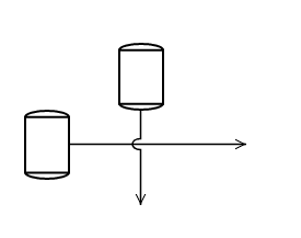
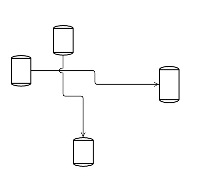
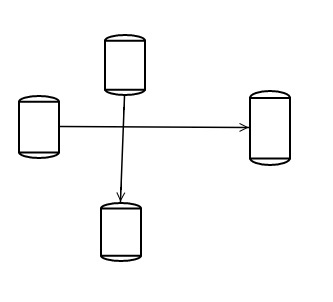
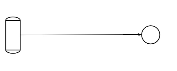
In our logic, Actually Nodes location spot not always comes from go.spot.Center. For each node have different port spot location(Not Center).
For example:

Node Template1 to make port:

     PortHelper.makePort("L", new go.Spot(0, 0.25, 0, 0), true, true),
    PortHelper.makePort("R", new go.Spot(1, 0.25, 0, 0), true, true),
    PortHelper.makePort("B", new go.Spot(0.5, 1, 0, 0), true, true)

NodeTemplate2 to make port:

   PortHelper.makePort("T", new go.Spot(0.5, 0, 0, 0), true, true),
    PortHelper.makePort("B", new go.Spot(0.5, 1, 0, 0), true, true),

    PortHelper.makePort("L1", new go.Spot(0, 0.1667, 0, 0), true, true),
    PortHelper.makePort("L2", new go.Spot(0, 0.5    , 0, 0), true, true),
    PortHelper.makePort("L3", new go.Spot(0, 0.8333, 0, 0), true, true),

    PortHelper.makePort("R1", new go.Spot(1, 0.1667, 0, 0), true, true),
    PortHelper.makePort("R2", new go.Spot(1, 0.5, 0, 0), true, true),
    PortHelper.makePort("R3", new go.Spot(1, 0.8333, 0, 0), true, true),    

PortHelper

export class PortHelper{
static makePort(name:any, spot:any, output:any, input:any) {

var GO = go.GraphObject.make;

return GO(go.Shape, "Square",
    {
        fill: null,
        stroke: null,
        strokeWidth: 1.5,
        desiredSize: new go.Size(7, 7),
        alignment: spot,
        portId: name,
        fromSpot: spot, toSpot: spot,
        fromLinkable: output, toLinkable: input,
        fromMaxLinks: 1, toMaxLinks: 1,
        cursor: "pointer"
    });

}
}
Without using LocationSpot to Spot.Center, Is any other way to place the two object’s in same axis(like FromPort and ToPort in same direction)

You’ll need to calculate the locations yourself, depending on which link you choose to be straight.

You can call GraphObject.getDocumentPoint with argument go.Spot.Center on both of the link’s ports (Link.fromPort and Link.toPort) to see how far apart the X or Y values are.

I am using Custom Link for LinkTemplate and Diagram.toolManager.linkingTool temporary Link.

In Link.computepoints(), I am trying to access this.fromPort.PortId. But While dragging the link, PortId it always returns empty and after dropped link it returns portId of the fromPort.

In this picture you can notice that, Port Id initially printing empty and after dropped it prints “R”

Did you have a question? What are you trying to accomplish?

Is that possible to get the fromPort.PortId in Link.computePoints(). If so Why I am getting the value of the portId only after the link dragging stopped .

You can look at the portId, but I do not imagine that that information should be essential to determining the route. The temporary link manipulated during linking will connect with temporary nodes/ports, and by default those nodes only have a single default port.