That should happen automatically when the FromSpot or ToSpot is a corner spot, such as Spot.TopRight.
But more generally, for orthogonally routed links there is an “end segment” that extends out perpendicularly from the side of the node. If you do not want that end segment to be orthogonal, you can customize the routing by overriding Route.ComputePoints to call the base method and then adjust the route points as desired.
Yeah seems ComputePoints is a good option but in that the length and shape of the links is as per the points you set and cannot be extended after that.
I came across an algorithm that you had posted in some other query. Its as below
public class CustomRoute : Route {
    protected override bool ComputePoints() {
      bool result = base.ComputePoints();
      if (result && this.PointsCount == 3) {
        Point s = GetPoint(0);
        Point m = GetPoint(1);
        Point e = GetPoint(2);
        double dx = e.X-s.X;
        double dy = e.Y-s.Y;
        double dist = Math.Sqrt(dx*dx + dy*dy);
        double space = dist/2-Math.Min(15, dist/3);
        double angle = GetAngle(dx, dy);
        double offX = Math.Cos(angle)*space;
        double offY = Math.Sin(angle)*space;
        SetPoint(1, new Point(m.X - offX, m.Y - offY));
        InsertPoint(2, new Point(m.X + offX, m.Y + offY));
      }
      return result;
    }
    public static double GetAngle(double x, double y) {
      double A;
      if (x == 0) {
        if (y > 0)
          A = Math.PI/2;
        else
          A = 3*Math.PI/2;
      } else if (y == 0) {
        if (x > 0)
          A = 0;
        else
          A = Math.PI;
      } else {
        if (Double.IsNaN(x) || Double.IsNaN(y)) return 0;
        A = Math.Atan(Math.Abs(y/x));
        if (x < 0 && y < 0) A -= Math.PI;
        else if (x < 0) A = Math.PI-A;
        else if (y < 0) A = -A;
      }
      return A;
    }
  }
This extension of Route will only give specific route points for the link and after which it cant be extended.
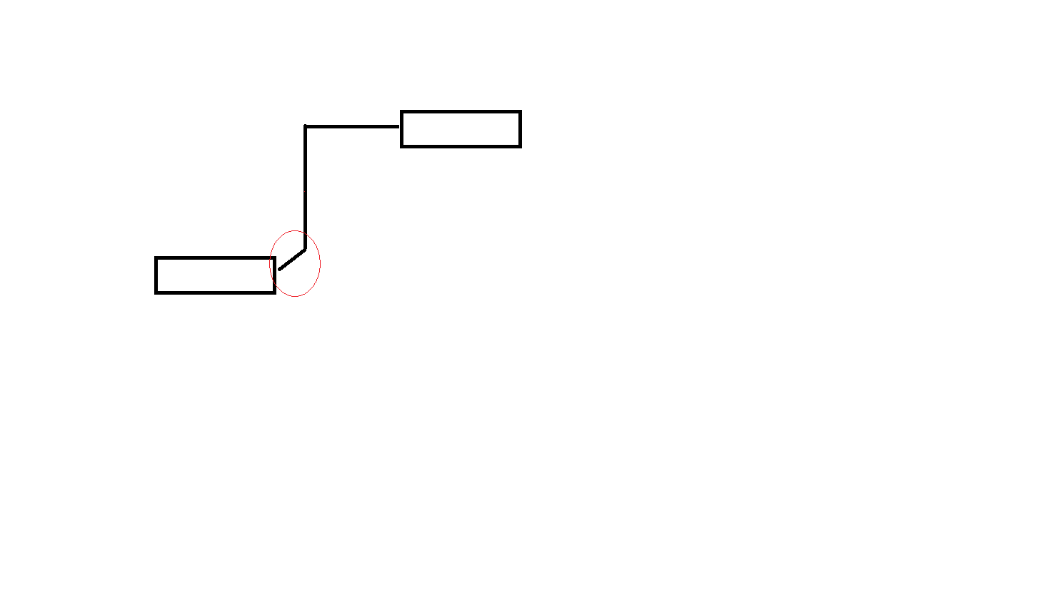
My requirement is that, from a specific node the link should be as orthogonal but when it connects to the other node it should be diagonally that too only at the small part near the ToNode(as per the image) and it should not be fixed. I should also be able to more the nodes around.
Yes, the code that you quoted is a good example of overriding Link.ComputePoints to let the default routing take place and then modify the route. In that case it modifies point #1 and inserts a point #2.
I was suggesting that you modify point #1 or point .PointsCount-2 to form a diagonal. If your links are Orthogonal, you also will need to modify point #2 or point .PointsCount-3.
I appreciate the suggestion but I came across another approach rather than getting angles and trigonometry. Seems Okay to me.
Below is the code.
protected override bool ComputePoints()
{
bool result = base.ComputePoints();
if (result)
{
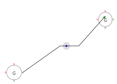
SetPoint(1, MidPoint);
InsertPoint(2, new Point(MidPoint.X + 50, MidPoint.Y));
InsertPoint(3, this.Link.ToNode.Location);
}
return result;
}
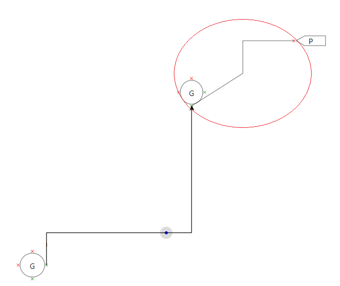
I am just making use of Midpoint and inserting points into Route accordingly. But I have a issue with this. Please follow the image.
If you could see at the ToNode the link should have been connected to the ToPort( i.e. the left x mark). But the Port class doesn’t provide Location property and as I have given the Location of the ToNode its going to center of the ToNode.
By any ways can I find the location of the ToNode’s port ?
Route.MidPoint cannot return a valid value until the route is complete. After all, if the route takes a circuitous path, the MidPoint of the route might be far away from the point bisecting a straight line between the two ports.
There are a bunch of methods on Route which are used by the built-in implementation of Route.ComputePoints.
I still think it would be best if you called the base method to get a “correct” route and if it returned true then adjusted the points to suit your particular needs.
Thanks for the response.
I think for my requirement using Route.MidPoint is Okay. and there would not be any links which are in circular path.
I achieved the requirement using the following code:
        <DataTemplate x:Key="LinkTemplate">
            <go:LinkPanel  go:Part.Selectable="True" go:Part.Reshapable="True" go:Part.LayerName="{Binding Path=Part.IsSelected, Converter={StaticResource selectedLayerConverter}}">

                <!--In the Below code we are using the custom class for routing of the link-->
                <go:Link.Route>
                    <local:CustomRoute RelinkableFrom="True" RelinkableTo="True" Curve="JumpOver"/>
                </go:Link.Route>
                <go:LinkShape Stroke="Black" StrokeThickness="1" StrokeDashArray="1, 1" />
            </go:LinkPanel>
        </DataTemplate>
The C# code would be:
 public class CustomRoute : Route
    {
        protected override bool ComputePoints()
        {
            bool result = base.ComputePoints();
            if (result)
            {
                //The following code adds the customized points to the route property
                var startPt = this.Link.Route.Points[0];
                var endPt = this.Link.Route.Points[1];
                SetPoint(1, new Point(MidPoint.X,startPt.Y));
                InsertPoint(2, MidPoint);
                InsertPoint(3, endPt);
            }
            return result;
        }
    }
The above implementation works perfectly but I would like to do a small enhancement here.
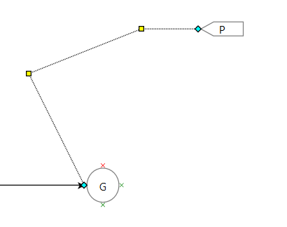
When I draw the link from P to G ( refering to the above diagram) it draws perfectly as needed.
Now I select the link connecting P and G nodes and make some changes to the link just like below:
now when I move G or P I expect that the link remain as above. But its getting reset to the diagonal which is because it calls the “ComputePoint()” again.
By any ways I can retain the link structure as above ?
That is what the Route.Adjusting property is for. Although your override of Route.ComputePoints needs to be smarter about inserting additional points, not doing it repeatedly.