Geometry bounds error

Hello.

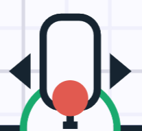
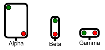
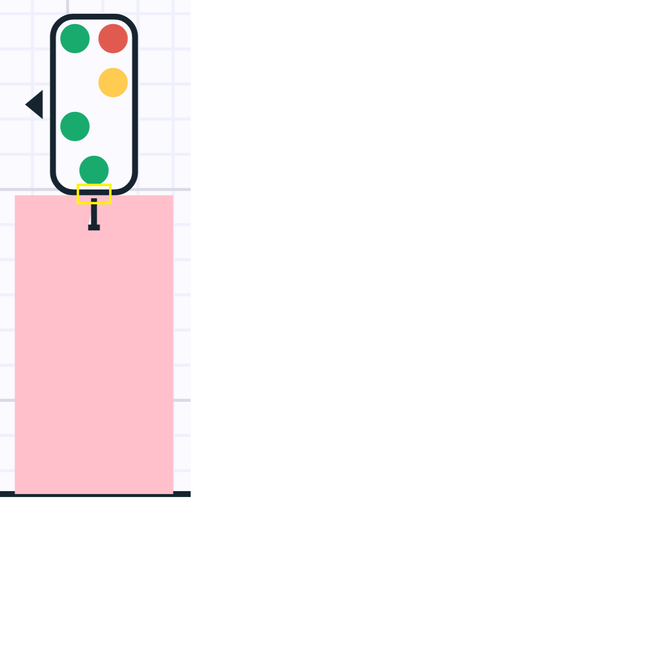
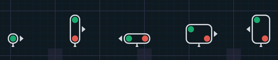
In our production code, we have a Go.js template that generates different configurations of signal types, as shown in the following image.

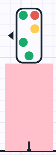
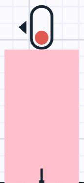
That worked great until we changed our vite configuration Go.js flag from ‘gojs’ to ‘gojs/release/go-debug.js’. After this change we get the following error in the browser console:

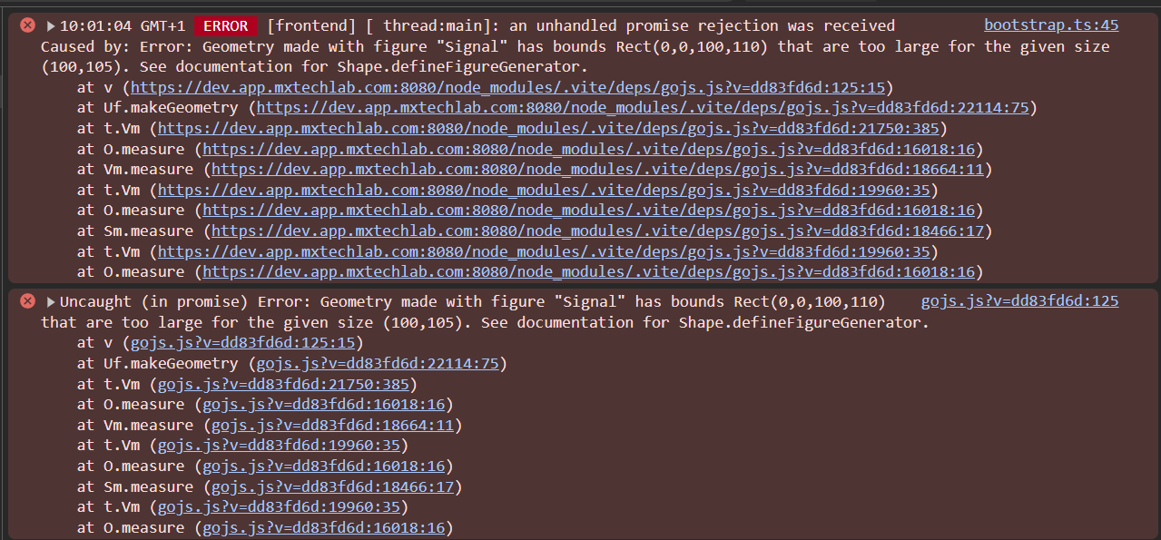
and the signals are not displayed at all.

The signal template code is:

import { BasicDirection } from '@/apps/types/common';
import {
  Node,
  Binding,
  Point,
  GraphObject,
  Spot,
  Panel,
  Shape,
  Geometry,
  PathFigure,
  PathSegment
} from 'gojs';

const ARROW_MARGIN = 2;
const ARROW_HEIGHT = 10;
const ARROW_WIDTH = 6;
const CIRCLE_RADIUS = 5;
const CIRCLE_MARGIN = 1;
const RADIUS = CIRCLE_RADIUS + 2 * CIRCLE_MARGIN;
const FOOT_HEIGHT = 5;
const FOOT_WIDTH = 2; // half the width

Shape.defineFigureGenerator('Signal', (_, width, height) => {
  const signalGeometry = new Geometry();

  const bodyPathFigure = new PathFigure(0, RADIUS, true);
  bodyPathFigure.add(new PathSegment(PathSegment.Arc, 180, 90, RADIUS, RADIUS, RADIUS, RADIUS)); // Top left corner
  bodyPathFigure.add(new PathSegment(PathSegment.Line, width - RADIUS, 0)); // Top line
  bodyPathFigure.add(
    new PathSegment(PathSegment.Arc, 270, 90, width - RADIUS, RADIUS, RADIUS, RADIUS)
  ); // Top right corner
  bodyPathFigure.add(new PathSegment(PathSegment.Line, width, height - RADIUS)); // Right line
  bodyPathFigure.add(
    new PathSegment(PathSegment.Arc, 0, 90, width - RADIUS, height - RADIUS, RADIUS, RADIUS)
  ); // Bottom right corner
  bodyPathFigure.add(new PathSegment(PathSegment.Line, RADIUS, height)); // Bottom line
  bodyPathFigure.add(
    new PathSegment(PathSegment.Arc, 90, 90, RADIUS, height - RADIUS, RADIUS, RADIUS)
  ); // Bottom left corner
  bodyPathFigure.add(new PathSegment(PathSegment.Line, 0, RADIUS)); // Left line

  signalGeometry.add(bodyPathFigure);

  const footPathFigure = new PathFigure(width / 2, height, true);
  footPathFigure.add(new PathSegment(PathSegment.Line, width / 2, height + FOOT_HEIGHT));
  footPathFigure.add(
    new PathSegment(PathSegment.Line, width / 2 + FOOT_WIDTH, height + FOOT_HEIGHT)
  );
  footPathFigure.add(
    new PathSegment(PathSegment.Line, width / 2 - FOOT_WIDTH, height + FOOT_HEIGHT)
  );

  signalGeometry.add(footPathFigure);

  return signalGeometry;
});

const mainSignalNodeTemplate = ($: typeof GraphObject.make): Node =>
  $(
    Node,
    'Auto',
    {
      rotationSpot: Spot.Center,
      locationSpot: Spot.Bottom,
      fromLinkable: false,
      toLinkable: false
    },
    new Binding('location', 'location', ({ x, y }) => new Point(x, y)),
    new Binding('layerName', 'layerName'),
    $(
      Panel,
      'Horizontal',
      $(
        Shape,
        'TriangleLeft',
        { width: ARROW_WIDTH, height: ARROW_HEIGHT, margin: ARROW_MARGIN, stroke: null },
        new Binding('fill', '', (modelData, shapeData: Shape) => {
          return shapeData.part?.data?.states.direction === BasicDirection.Reverse
            ? modelData.borderColorDefault
            : 'transparent';
        }).ofModel()
      ),
      $(
        Panel,
        'Auto',
        $(
          Shape,
          'Signal',
          { strokeWidth: 2 },
          new Binding('fill', 'svgIconBackgroundColor').ofModel(),
          new Binding('stroke', 'borderColorDefault').ofModel()
        ),
        $(Panel, 'Vertical', new Binding('itemArray', 'states', states => states.lampStates), {
          itemTemplate: $(
            Panel,
            'Auto',
            { margin: CIRCLE_MARGIN },
            $(Panel, 'Horizontal', new Binding('itemArray', ''), {
              itemTemplate: $(
                Panel,
                'Auto',
                { margin: CIRCLE_MARGIN },
                $(
                  Shape,
                  'Circle',
                  { width: 2 * CIRCLE_RADIUS, height: 2 * CIRCLE_RADIUS, stroke: null },
                  new Binding('fill', '', (modelData, sd) => {
                    const key = sd.panel.data;
                    const value = modelData[key];
                    return value ?? 'transparent';
                  }).ofModel()
                )
              )
            })
          )
        })
      ),
      $(
        Shape,
        'TriangleRight',
        { width: ARROW_WIDTH, height: ARROW_HEIGHT, margin: ARROW_MARGIN, stroke: null },
        new Binding('fill', '', (modelData, shapeData: Shape) => {
          return shapeData.part?.data?.states.direction === BasicDirection.Nominal
            ? modelData.borderColorDefault
            : 'transparent';
        }).ofModel()
      )
    )
  );

export default mainSignalNodeTemplate;

I tried to make the geometry dimensions smaller but I still get errors regarding the bounds. Our current Go.js license allows us only to see minified Go,js code while debugging so it is hard to debug this extensively.

I wonder if you could point me to the right direction? We want this to work even for signals having multiple lamps/states so I am not sure how this can be solved generically so that the bounds do not exceed the figure size.

Best regards,
Fotis

It appears that the problem is that you have added something to the bottom of the rectangular area. Since that rectangular area is given the full height given by height, anything you add will necessarily extend beyond the requested height. You have to make that rectangular area shorter than the given height so that there’s room for that “footer”.

Also, when you have “fixed” size segments, you have to be careful what happens when the given width or height are smaller than you expect. For example, what happens when the Shape needs to be 3x3? Surely it cannot use the FOOTER_WIDTH and FOOTER_HEIGHT that you assigned as constants.

Here’s my modification of your code. I don’t know if the policies I have chosen are what you want – please consider the changes carefully.

const CIRCLE_RADIUS = 5;
const CIRCLE_MARGIN = 1;
const RADIUS = CIRCLE_RADIUS + 2 * CIRCLE_MARGIN;
const FOOT_HEIGHT = 5;
const FOOT_WIDTH = 2; // half the width

go.Shape.defineFigureGenerator('Signal', (_, width, height) => {
  const fw = Math.min(FOOT_WIDTH, width/2);
  const fh = Math.min(FOOT_HEIGHT, height/2);
  const w = width;
  const h = height - fh;
  let r = Math.min(RADIUS, Math.min(w/3, h/3));
  if (r < 1) r = 0;

  const signalGeometry = new go.Geometry();

  const bodyPathFigure = new go.PathFigure(0, r, true);
  if (r > 0) bodyPathFigure.add(new go.PathSegment(go.PathSegment.Arc, 180, 90, r, r, r, r)); // Top left corner
  bodyPathFigure.add(new go.PathSegment(go.PathSegment.Line, w - r, 0)); // Top line
  if (r > 0) bodyPathFigure.add(new go.PathSegment(go.PathSegment.Arc, 270, 90, w - r, r, r, r)); // Top right corner
  bodyPathFigure.add(new go.PathSegment(go.PathSegment.Line, w, h - r)); // Right line
  if (r > 0) bodyPathFigure.add(new go.PathSegment(go.PathSegment.Arc, 0, 90, w - r, h - r, r, r)); // Bottom right corner
  bodyPathFigure.add(new go.PathSegment(go.PathSegment.Line, r, h)); // Bottom line
  if (r > 0) bodyPathFigure.add(new go.PathSegment(go.PathSegment.Arc, 90, 90, r, h - r, r, r)); // Bottom left corner
  bodyPathFigure.add(new go.PathSegment(go.PathSegment.Line, 0, r).close()); // Left line

  signalGeometry.add(bodyPathFigure);

  const footPathFigure = new go.PathFigure(w / 2, h, false);  // not filled!
  footPathFigure.add(new go.PathSegment(go.PathSegment.Line, w / 2, h + fh));
  footPathFigure.add(new go.PathSegment(go.PathSegment.Line, w / 2 + fw, h + fh));
  footPathFigure.add(new go.PathSegment(go.PathSegment.Line, w / 2 - fw, h + fh));

  signalGeometry.add(footPathFigure);

  return signalGeometry;
});

Hello Walter and thanks for your fast reply, highly appreciated!

That almost worked, the issue I have now is that the created circle is not aligned properly, which I have fixed by changing the CIRCLE_MARGIN in the code above, not sure if this is the best way though?).

image

Regarding your other comment, I think that you are right, it is probably better if all the shape dimensions are relative to the incoming width and height (if I interpreted your comment correctly?).

Ah, that’s what those two constants are for. Yes, again, you really cannot use constants when the width or height is variable.

Perhaps instead of using fixed sizes/distances for those circle(s) you can use a Spot alignment for the elements in a “Spot” Panel rather than in a “Vertical” Panel. Panels | GoJS That way the circles are aligned according to fractional distances rather than absolute distances.

Oh, wait – I didn’t notice that there were nested panels there – “Horizontal” panels inside the “Vertical” panel. If there are always going to be zero, one, or two circles, instead of using nested “Horizontal” Panels, just using a single “Spot” Panel, maybe you could assign the alignment for each element Panel holding a “Circle” Shape using a Binding whose conversion function would return either new go.Spot(0, 0, CIRCLE_RADIUS, CIRCLE_RADIUS) or new go.Spot(1, 1, -CIRCLE_RADIUS, -CIRCLE_RADIUS). Hmmm, that isn’t exactly right – you’ll need to play with that to get the numbers correct, especially if the CIRCLE_RADIUS is too big for the given overall size.

Ok, thanks. Not sure I follow completely though. I think that I need to try the different options a bit and maybe get back to you if something is unclear. I need to experiment with the signal figure as well as the curved lines appear more squared than in the original version. Thanks for the tips I will keep investigating. Have a great day!

Try this:

<!DOCTYPE html>
<html>
<head>
  <title>Minimal GoJS Sample</title>
  <!-- Copyright 1998-2024 by Northwoods Software Corporation. -->
</head>
<body>
  <div id="myDiagramDiv" style="border: solid 1px black; width:100%; height:400px"></div>
  <textarea id="mySavedModel" style="width:100%;height:250px"></textarea>

  <script src="https://cdn.jsdelivr.net/npm/gojs/release/go-debug.js"></script>
  <script id="code">
const myDiagram =
  new go.Diagram("myDiagramDiv", {
      "undoManager.isEnabled": true,
      "ModelChanged": e => {     // just for demonstration purposes,
        if (e.isTransactionFinished) {  // show the model data in the page's TextArea
          document.getElementById("mySavedModel").textContent = e.model.toJson();
        }
      }
    });

const CIRCLE_RADIUS = 5;
const CIRCLE_MARGIN = 1;
const RADIUS = CIRCLE_RADIUS + 2 * CIRCLE_MARGIN;
const FOOT_HEIGHT = 5;
const FOOT_WIDTH = 2; // half the width

go.Shape.defineFigureGenerator('Signal', (_, width, height) => {
  const fw = Math.min(FOOT_WIDTH, width/2);
  const fh = Math.min(FOOT_HEIGHT, height/2);
  const w = width;
  const h = height - fh;
  let r = Math.min(RADIUS, Math.min(w/3, h/3));
  if (r < 1) r = 0;

  const signalGeometry = new go.Geometry();

  const bodyPathFigure = new go.PathFigure(0, r, true);
  if (r > 0) bodyPathFigure.add(new go.PathSegment(go.PathSegment.Arc, 180, 90, r, r, r, r)); // Top left corner
  bodyPathFigure.add(new go.PathSegment(go.PathSegment.Line, w - r, 0)); // Top line
  if (r > 0) bodyPathFigure.add(new go.PathSegment(go.PathSegment.Arc, 270, 90, w - r, r, r, r)); // Top right corner
  bodyPathFigure.add(new go.PathSegment(go.PathSegment.Line, w, h - r)); // Right line
  if (r > 0) bodyPathFigure.add(new go.PathSegment(go.PathSegment.Arc, 0, 90, w - r, h - r, r, r)); // Bottom right corner
  bodyPathFigure.add(new go.PathSegment(go.PathSegment.Line, r, h)); // Bottom line
  if (r > 0) bodyPathFigure.add(new go.PathSegment(go.PathSegment.Arc, 90, 90, r, h - r, r, r)); // Bottom left corner
  bodyPathFigure.add(new go.PathSegment(go.PathSegment.Line, 0, r).close()); // Left line

  signalGeometry.add(bodyPathFigure);

  const footPathFigure = new go.PathFigure(w / 2, h, false);  // not filled!
  footPathFigure.add(new go.PathSegment(go.PathSegment.Line, w / 2, h + fh));
  footPathFigure.add(new go.PathSegment(go.PathSegment.Line, w / 2 + fw, h + fh));
  footPathFigure.add(new go.PathSegment(go.PathSegment.Line, w / 2 - fw, h + fh));

  signalGeometry.add(footPathFigure);

  return signalGeometry;
});

myDiagram.nodeTemplate =
  new go.Node("Vertical", {
      selectionObjectName: "SHAPE",
      resizable: true, resizeObjectName: "SHAPE"
    })
    .add(
      new go.Panel("Auto")
        .add(
          new go.Shape("Signal", { name: "SHAPE", width: 50, height: 80, fill: "white", strokeWidth: 4, minSize: new go.Size(17, 22) })
            .bindTwoWay("desiredSize", "size", go.Size.parse, go.Size.stringify),
          new go.Shape("Circle", { width: 10, height: 10, fill: "green", alignment: new go.Spot(0, 0, 5, 5) }),
          new go.Shape("Circle", { width: 10, height: 10, fill: "red", alignment: new go.Spot(1, 1, -5, -10) })
        ),
      new go.TextBlock()
        .bind("text")
    );

myDiagram.model = new go.GraphLinksModel(
[
  { key: 1, text: "Alpha" },
]);
  </script>
</body>
</html>

image

Hi Walter and thanks for the time you have spent on this. I tried your latest example in a Go.js playground and it seems to work fine, but it is a simplified example with ‘Circles’ defined explicitly.

What I am struggling with is that in my case I need the extra layers in order to be able to generate as many circles as needed (like having a 2D visual array) that will expand the signal shape accordingly. That’s why I use the lampStates in the panels. The lampStates are calculated based on the circle’s x, y position in the 2D array of lamps, i.e.:

function getMainSignalState(node: VisualizationNode) {
  const { lampStates, direction } = node.state as SignalState;
  const { maxX, maxY } = lampStates.reduce(
    (acc, { posX, posY }) => ({
      maxX: Math.max(acc.maxX, Number(posX)),
      maxY: Math.max(acc.maxY, Number(posY))
    }),
    { maxX: 0, maxY: 0 }
  );

  const states = [];
  for (let row = 1; row <= maxY; row += 1) {
    const rowStates = [];
    for (let col = 1; col <= maxX; col += 1) {
      const lampState = lampStates.find(s => Number(s.posX) === col && Number(s.posY) === row);
      const color = lampState ? MainSignalMap.get(lampState?.color) : 'transparent';
      rowStates.push(color);
    }
    states.push(rowStates);
  }

  return {
    ...node,
    states: { lampStates: states, direction },
    ... more properties
  };
}

Also there are panels drawing a triangle to the left or right of the signal.

Based on all the above, it is not that trivial to create a Signal shape that is both calculated dynamically based on the incoming width and height and also accommodate inside it the varying number of circles with correct margins. I noticed for example the changing a panel margin led to reducing the height of the Signal shape. I tried to use Spot alignment instead but that misplaced some of the lamps so it is difficult to make it generic. I think that the first step to solve this is to go through and re-think which panels I want to use for it part.

Just make the circle into a Panel.itemTemplate, by containing the Shape in a Panel, and add appropriate bindings.

Then put that into an “Auto” Panel with an unseen but visible main Shape element that stretches to fill the available area, and uses that itemTemplate.

That available area is inside an “Auto” Panel that has your “Signal” figure Shape as its main/border element. Note that I have added settings of Geometry.spot1 and spot2 so that the “Auto” Panel knows what available area there is inside that particular “Signal” Shape.

<!DOCTYPE html>
<html>
<head>
  <title>Minimal GoJS Sample</title>
  <!-- Copyright 1998-2024 by Northwoods Software Corporation. -->
</head>
<body>
  <div id="myDiagramDiv" style="border: solid 1px black; width:100%; height:400px"></div>
  <textarea id="mySavedModel" style="width:100%;height:250px"></textarea>

  <script src="https://cdn.jsdelivr.net/npm/gojs/release/go-debug.js"></script>
  <script id="code">
const myDiagram =
  new go.Diagram("myDiagramDiv", {
      "undoManager.isEnabled": true,
      "ModelChanged": e => {     // just for demonstration purposes,
        if (e.isTransactionFinished) {  // show the model data in the page's TextArea
          document.getElementById("mySavedModel").textContent = e.model.toJson();
        }
      }
    });

const CIRCLE_RADIUS = 5;
const CIRCLE_MARGIN = 1;
const RADIUS = CIRCLE_RADIUS + 2 * CIRCLE_MARGIN;
const FOOT_HEIGHT = 5;
const FOOT_WIDTH = 2; // half the width

go.Shape.defineFigureGenerator('Signal', (_, width, height) => {
  const fw = Math.min(FOOT_WIDTH, width/2);
  const fh = Math.min(FOOT_HEIGHT, height/2);
  const w = width;
  const h = height - fh;
  let r = Math.min(RADIUS, Math.min(w/3, h/3));
  if (r < 1) r = 0;

  const signalGeometry = new go.Geometry();

  const bodyPathFigure = new go.PathFigure(0, r, true);
  if (r > 0) bodyPathFigure.add(new go.PathSegment(go.PathSegment.Arc, 180, 90, r, r, r, r)); // Top left corner
  bodyPathFigure.add(new go.PathSegment(go.PathSegment.Line, w - r, 0)); // Top line
  if (r > 0) bodyPathFigure.add(new go.PathSegment(go.PathSegment.Arc, 270, 90, w - r, r, r, r)); // Top right corner
  bodyPathFigure.add(new go.PathSegment(go.PathSegment.Line, w, h - r)); // Right line
  if (r > 0) bodyPathFigure.add(new go.PathSegment(go.PathSegment.Arc, 0, 90, w - r, h - r, r, r)); // Bottom right corner
  bodyPathFigure.add(new go.PathSegment(go.PathSegment.Line, r, h)); // Bottom line
  if (r > 0) bodyPathFigure.add(new go.PathSegment(go.PathSegment.Arc, 90, 90, r, h - r, r, r)); // Bottom left corner
  bodyPathFigure.add(new go.PathSegment(go.PathSegment.Line, 0, r).close()); // Left line

  signalGeometry.add(bodyPathFigure);

  const footPathFigure = new go.PathFigure(w / 2, h, false);  // not filled!
  footPathFigure.add(new go.PathSegment(go.PathSegment.Line, w / 2, h + fh));
  footPathFigure.add(new go.PathSegment(go.PathSegment.Line, w / 2 + fw, h + fh));
  footPathFigure.add(new go.PathSegment(go.PathSegment.Line, w / 2 - fw, h + fh));

  signalGeometry.add(footPathFigure);

  signalGeometry.spot1 = new go.Spot(0, 0, r/2, r/2);
  signalGeometry.spot2 = new go.Spot(1, 1, -r/2, -r/2-fh)

  return signalGeometry;
});

myDiagram.nodeTemplate =
  new go.Node("Vertical", {
      selectionObjectName: "SHAPE",
      resizable: true, resizeObjectName: "SHAPE"
    })
    .bindTwoWay("location", "loc", go.Point.parse, go.Point.stringify)
    .add(
      new go.Panel("Auto", { name: "SHAPE", minSize: new go.Size(17, 22) })
        .bindTwoWay("desiredSize", "size", go.Size.parse, go.Size.stringify)
        .add(
          new go.Shape("Signal", {
              isPanelMain: true,
              stretch: go.Stretch.Fill,
              fill: "white", strokeWidth: 2,
            }),
          new go.Panel("Auto", {
              stretch: go.Stretch.Fill,
              itemTemplate:
                new go.Panel({ alignment: go.Spot.BottomLeft })
                  .bind("alignment", "a", go.Spot.parse)
                  .add(
                    new go.Shape("Circle", { width: 10, height: 10, strokeWidth: 0 })
                      .bind("fill", "c")
                  )
            })
            .bind("itemArray", "lights")
            .add(
              new go.Shape({ isPanelMain: true, stretch: go.Stretch.Fill, fill: null, strokeWidth: 0 })
            )
        ),
      new go.TextBlock()
          .bind("text")
    );

myDiagram.model = new go.GraphLinksModel(
[
  { key: 1, text: "Alpha", lights: [{ c: "green", a: "0 0" }, { c: "blue", a: "0.5 0.5" }, { c: "red", a: "1 1" }], loc: "0 0", size: "50 100" },
  { key: 2, text: "Beta", lights: [{ c: "green", a: "0.8 0.2" }, { c: "purple", a: "0.2 0.8" }], loc: "100 0", size: "80 22" },
  { key: 3, text: "Gamma", lights: [{ c: "green", a: "0.8 0.2" }, { c: "purple", a: "0.2 0.8" }], loc: "200 0", size: "17 80" }
]);
  </script>
</body>
</html>

Thank you very much Walter! Your last post was really insightful so I will build my solution on that.

Hi Walter. Sorry to disturb you again but I didn’t have the time to test this until now and I have a small question.

I have chosen a slightly different solution that is also dynamic (no hardcoded width or height) by drawing a signal image that takes 90% and a signal foot image that takes 10% of the available area and placed them in a Vertical panel. The new code is attached below.

The only issue I have now is that the signal foot image becomes quite tall and wide (marked with pink background in the attached images below to make it visible) and I cannot understand why.

I tried to limit at least the height of the signal foot image so that there is no vertical space between it and the signal image to no avail, i.e., I cannot make the outer height (shown in pink) to match the internal signal foot height (the extra margin is always there). Setting the height changes the outer height only. Could you perhaps help me understand why this is happening?

import { BasicDirection } from '@/apps/types/common';
import { GoJSLayer } from '@/typings/layers';
import {
  Node,
  Binding,
  Point,
  GraphObject,
  Spot,
  Panel,
  Shape,
  Geometry,
  PathFigure,
  PathSegment
} from 'gojs';

const ARROW_MARGIN = 2;
const ARROW_HEIGHT = 10;
const ARROW_WIDTH = 6;
const CIRCLE_RADIUS = 5;
const CIRCLE_MARGIN = 1;
const RADIUS = CIRCLE_RADIUS + 2 * CIRCLE_MARGIN;
const FOOT_WIDTH = 2; // half the width

Shape.defineFigureGenerator('Signal', (_, width, height) => {
  const signalGeometry = new Geometry();
  if (width > 0 && height > 0) {
    const signalHeight = height;
    const bodyPathFigure = new PathFigure(0, RADIUS, true);
    bodyPathFigure.add(new PathSegment(PathSegment.Arc, 180, 90, RADIUS, RADIUS, RADIUS, RADIUS)); // Top left corner
    bodyPathFigure.add(new PathSegment(PathSegment.Line, width - RADIUS, 0)); // Top line
    bodyPathFigure.add(
      new PathSegment(PathSegment.Arc, 270, 90, width - RADIUS, RADIUS, RADIUS, RADIUS)
    ); // Top right corner
    bodyPathFigure.add(new PathSegment(PathSegment.Line, width, signalHeight - RADIUS)); // Right line
    bodyPathFigure.add(
      new PathSegment(PathSegment.Arc, 0, 90, width - RADIUS, signalHeight - RADIUS, RADIUS, RADIUS)
    ); // Bottom right corner
    bodyPathFigure.add(new PathSegment(PathSegment.Line, RADIUS, signalHeight)); // Bottom line
    bodyPathFigure.add(
      new PathSegment(PathSegment.Arc, 90, 90, RADIUS, signalHeight - RADIUS, RADIUS, RADIUS)
    ); // Bottom left corner
    bodyPathFigure.add(new PathSegment(PathSegment.Line, 0, RADIUS)); // Left line
    signalGeometry.add(bodyPathFigure);
  }
  return signalGeometry;
});

Shape.defineFigureGenerator('SignalFoot', (_, width, height) => {
  const signalFootGeometry = new Geometry();
  if (width > 0 && height > 0) {
    const signalHeight = 0.9 * height;
    const signalFootHeight = 0.1 * height;
    const footPathFigure = new PathFigure(width / 2, signalHeight, true);
    footPathFigure.add(
      new PathSegment(PathSegment.Line, width / 2, signalHeight + signalFootHeight)
    );
    footPathFigure.add(
      new PathSegment(PathSegment.Line, width / 2 + FOOT_WIDTH, signalHeight + signalFootHeight)
    );
    footPathFigure.add(
      new PathSegment(PathSegment.Line, width / 2 - FOOT_WIDTH, signalHeight + signalFootHeight)
    );
    signalFootGeometry.add(footPathFigure);
  }
  return signalFootGeometry;
});

const mainSignalNodeTemplate = ($: typeof GraphObject.make): Node =>
  $(
    Node,
    'Vertical',
    {
      rotationSpot: Spot.Center,
      locationSpot: Spot.Bottom,
      fromLinkable: false,
      toLinkable: false,
    },
    new Binding('location', 'location', ({ x, y }) => new Point(x, y)),
    new Binding('layerName', 'layerName'),
    $(
      Panel,
      'Horizontal',
      $(
        Shape,
        'TriangleLeft',
        { width: ARROW_WIDTH, height: ARROW_HEIGHT, margin: ARROW_MARGIN, stroke: null },
        new Binding('fill', '', (modelData, shapeData: Shape) => {
          return shapeData.part?.data?.states.direction === BasicDirection.Reverse
            ? modelData.borderColorDefault
            : 'transparent';
        }).ofModel()
      ),
      $(
        Panel,
        'Auto',
        $(
          Shape,
          'Signal',
          { strokeWidth: 2 },
          new Binding('fill', 'svgIconBackgroundColor').ofModel(),
          new Binding('stroke', 'borderColorDefault').ofModel()
        ),
        $(Panel, 'Vertical', new Binding('itemArray', 'states', states => states.lampStates), {
          itemTemplate: $(
            Panel,
            'Auto',
            { margin: CIRCLE_MARGIN },
            $(Panel, 'Horizontal', new Binding('itemArray', ''), {
              itemTemplate: $(
                Panel,
                'Auto',
                { margin: CIRCLE_MARGIN },
                $(
                  Shape,
                  'Circle',
                  {
                    width: 2 * CIRCLE_RADIUS,
                    height: 2 * CIRCLE_RADIUS,
                    stroke: null
                  },
                  new Binding('fill', '', (modelData, sd) => {
                    const key = sd.panel.data;
                    const value = modelData[key];
                    return value ?? 'transparent';
                  }).ofModel()
                )
              )
            })
          )
        })
      ),
      $(
        Shape,
        'TriangleRight',
        { width: ARROW_WIDTH, height: ARROW_HEIGHT, margin: ARROW_MARGIN, stroke: null },
        new Binding('fill', '', (modelData, shapeData: Shape) => {
          return shapeData.part?.data?.states.direction === BasicDirection.Nominal
            ? modelData.borderColorDefault
            : 'transparent';
        }).ofModel()
      )
    ),
    $(
      Panel,
      'Auto',
      $(
        Shape,
        'SignalFoot',
        { strokeWidth: 2 },
        { background: 'pink' },
        new Binding('fill', 'svgIconBackgroundColor').ofModel(),
        new Binding('stroke', 'borderColorDefault').ofModel()
      )
    )
  );

export default mainSignalNodeTemplate;

Example 1:

Example 2:
image

It doesn’t make sense to have an “Auto” Panel that only has one element (a Shape in this case).

That Shape doesn’t have a set desiredSize (a.k.a. width and height), so it gets the default size of 100x100.

I see, good comment. Removing the auto panel around ‘SignalFoot’ didn’t help with the issue though so maybe there are more panels that are misconfigured.

But what size should that “SignalFoot” Shape have?

According to the calculations in the figure it should be 10% of image height x FOOT_WIDTH. I changed the code generating the signal foot image to the following. Now the foot has moved upwards but there is still a gap between it and signal image and the extra margin is also there:

Updated code:

Shape.defineFigureGenerator('SignalFoot', (_, width, height) => {
  const signalFootGeometry = new Geometry();
  if (width > 0 && height > 0) {
    const signalFootHeight = 0.1 * height;
    const footPathFigure = new PathFigure(width / 2, 0, true);
    footPathFigure.add(new PathSegment(PathSegment.Line, width / 2, signalFootHeight));
    footPathFigure.add(new PathSegment(PathSegment.Line, width / 2 + FOOT_WIDTH, signalFootHeight));
    footPathFigure.add(new PathSegment(PathSegment.Line, width / 2 - FOOT_WIDTH, signalFootHeight));
    signalFootGeometry.add(footPathFigure);
  }
  return signalFootGeometry;
});

Result:

Hi again. I have now managed to make it work at least in all the scenarios I have tested. I attach the final code here in case someone else benefits from it. Thanks for your help Walter, I have learned many new things!

import { BasicDirection } from '@/apps/types/common';
import { GoJSLayer } from '@/typings/layers';
import {
  Node,
  Binding,
  Point,
  GraphObject,
  Spot,
  Panel,
  Shape,
  Geometry,
  PathFigure,
  PathSegment,
  Size,
  Margin
} from 'gojs';

const SIGNAL_FOOT_MARGIN = 2;
const ARROW_MARGIN = 2;
const ARROW_HEIGHT = 10;
const ARROW_WIDTH = 6;
const CIRCLE_RADIUS = 5;
const CIRCLE_MARGIN = 1;
const RADIUS = CIRCLE_RADIUS + 2 * CIRCLE_MARGIN;
const FOOT_HEIGHT = 5;
const FOOT_WIDTH = 2; // half the width

Shape.defineFigureGenerator('Signal', (_, width, height) => {
  const signalGeometry = new Geometry();
  if (width > 0 && height > 0) {
    const bodyPathFigure = new PathFigure(0, RADIUS, true);
    bodyPathFigure.add(new PathSegment(PathSegment.Arc, 180, 90, RADIUS, RADIUS, RADIUS, RADIUS)); // Top left corner
    bodyPathFigure.add(new PathSegment(PathSegment.Line, width - RADIUS, 0)); // Top line
    bodyPathFigure.add(
      new PathSegment(PathSegment.Arc, 270, 90, width - RADIUS, RADIUS, RADIUS, RADIUS)
    ); // Top right corner
    bodyPathFigure.add(new PathSegment(PathSegment.Line, width, height - RADIUS)); // Right line
    bodyPathFigure.add(
      new PathSegment(PathSegment.Arc, 0, 90, width - RADIUS, height - RADIUS, RADIUS, RADIUS)
    ); // Bottom right corner
    bodyPathFigure.add(new PathSegment(PathSegment.Line, RADIUS, height)); // Bottom line
    bodyPathFigure.add(
      new PathSegment(PathSegment.Arc, 90, 90, RADIUS, height - RADIUS, RADIUS, RADIUS)
    ); // Bottom left corner
    bodyPathFigure.add(new PathSegment(PathSegment.Line, 0, RADIUS)); // Left line
    signalGeometry.add(bodyPathFigure);
  }
  return signalGeometry;
});

Shape.defineFigureGenerator('SignalFoot', (_, width, height) => {
  const signalFootGeometry = new Geometry();
  if (width > 0 && height > 0) {
    const footPathFigure = new PathFigure(width / 2, height - FOOT_HEIGHT, true);
    footPathFigure.add(new PathSegment(PathSegment.Line, width / 2, height));
    footPathFigure.add(new PathSegment(PathSegment.Line, width / 2 + FOOT_WIDTH, height));
    footPathFigure.add(new PathSegment(PathSegment.Line, width / 2 - FOOT_WIDTH, height));
    signalFootGeometry.add(footPathFigure);
  }
  return signalFootGeometry;
});

const mainSignalNodeTemplate = ($: typeof GraphObject.make): Node =>
  $(
    Node,
    'Vertical',
    {
      rotationSpot: Spot.Center,
      locationSpot: Spot.Bottom,
      fromLinkable: false,
      toLinkable: false
    },
    new Binding('location', 'location', ({ x, y }) => new Point(x, y)),
    new Binding('layerName', 'layerName'),
    $(
      Panel,
      'Horizontal',
      $(
        Shape,
        'TriangleLeft',
        { width: ARROW_WIDTH, height: ARROW_HEIGHT, margin: ARROW_MARGIN, stroke: null },
        new Binding('fill', '', (modelData, shapeData: Shape) => {
          return shapeData.part?.data?.states.direction === BasicDirection.Reverse
            ? modelData.borderColorDefault
            : 'transparent';
        }).ofModel()
      ),
      $(
        Panel,
        'Auto',
        $(
          Shape,
          'Signal',
          { strokeWidth: 2 },
          new Binding('fill', 'svgIconBackgroundColor').ofModel(),
          new Binding('stroke', 'borderColorDefault').ofModel()
        ),
        $(Panel, 'Vertical', new Binding('itemArray', 'states', states => states.lampStates), {
          itemTemplate: $(
            Panel,
            'Auto',
            { margin: CIRCLE_MARGIN },
            $(Panel, 'Horizontal', new Binding('itemArray', ''), {
              itemTemplate: $(
                Panel,
                'Auto',
                { margin: CIRCLE_MARGIN },
                $(
                  Shape,
                  'Circle',
                  {
                    width: 2 * CIRCLE_RADIUS,
                    height: 2 * CIRCLE_RADIUS,
                    stroke: null
                  },
                  new Binding('fill', '', (modelData, sd) => {
                    const key = sd.panel.data;
                    const value = modelData[key];
                    return value ?? 'transparent';
                  }).ofModel()
                )
              )
            })
          )
        })
      ),
      $(
        Shape,
        'TriangleRight',
        { width: ARROW_WIDTH, height: ARROW_HEIGHT, margin: ARROW_MARGIN, stroke: null },
        new Binding('fill', '', (modelData, shapeData: Shape) => {
          return shapeData.part?.data?.states.direction === BasicDirection.Nominal
            ? modelData.borderColorDefault
            : 'transparent';
        }).ofModel()
      )
    ),
    $(
      Shape,
      'SignalFoot',
      {
        strokeWidth: 2,
        desiredSize: new Size(2 * FOOT_WIDTH, FOOT_HEIGHT),
        margin: new Margin(-SIGNAL_FOOT_MARGIN, 0, 0, 0)
      },
      new Binding('fill', 'svgIconBackgroundColor').ofModel(),
      new Binding('stroke', 'borderColorDefault').ofModel()
    )
  );

export default mainSignalNodeTemplate;