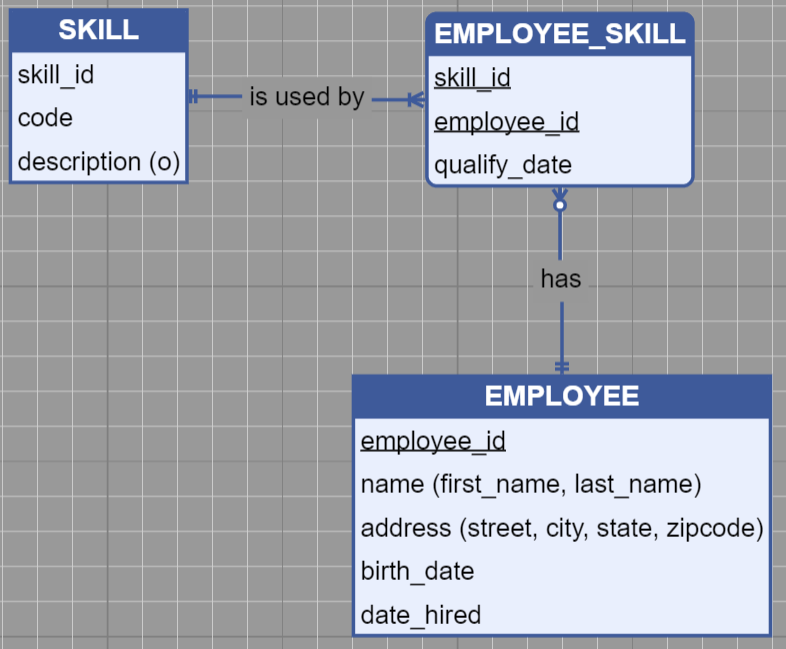
I have a dilemma; I can link two nodes but can’t move the nodes on the diagram, or I can move the nodes on the diagram but can’t link two nodes. Is it possible to be able to do both? I found something that works somewhat, but to link nodes I need to click a one pixel border of the node and drag which is nearly impossible. Here is my code:
// creates the node template for each entity
fileDiagram.nodeTemplate =
$(go.Node, "Auto",
	{
		defaultStretch: go.GraphObject.Horizontal,
		selectionAdorned: true,
		layoutConditions: go.Part.LayoutStandard & ~go.Part.LayoutNodeSized
	},

	// binds the location of the node
	new go.Binding("location", "location").makeTwoWay(),

	// creates the entity
	 $(go.Panel, "Auto",
		$(go.Shape, "Rectangle",
			{
				fill: "#eaeffd",
				stroke: "#3c599b",
				strokeWidth: 2,

				portId: "",
				background: "transparent",

				// allows links to/from all sides
				fromSpot: go.Spot.AllSides,
				toSpot: go.Spot.AllSides,

				// allows drawing links from or to this port
				fromLinkable: true,
				toLinkable: true,

				// allows drawing links within the same node
				fromLinkableSelfNode: true,
				toLinkableSelfNode: true,

				// allows duplicate linking
				fromLinkableDuplicates: true,
				toLinkableDuplicates: true,
				cursor: "pointer"
			},
			// sets the port for binding between two nodes
			new go.Binding("portId", "name"),
			new go.Binding("figure", "figure").makeTwoWay()
		)
	),

	// creates the node table
	$(go.Panel, "Vertical",

		$(go.Panel, "Auto",

			// stretches the header of the table to fill the node
			{
				stretch: go.GraphObject.Horizontal
			},

			// sets the fill and stroke of the header of the node
			$(go.Shape, "RoundedTopRectangle",
				{
					fill: "#3c599b",
					stroke: null
				}
			),
			// $(go.RowColumnDefinition, { row: 1, separatorStroke: "#3c599b" }),
			// sets the header text style and grabs the text from the binding
			$(go.TextBlock,
				{
					name: "ENTITY",
					row: 0,
					alignment: go.Spot.Center,
					margin: 3,
					stroke: "white",
					textAlign: "center",
					font: "bold 12pt sans-serif",
					cursor: "text",
					editable: true
				},
				new go.Binding("text", "key", function(key) { return key.toUpperCase() }).makeTwoWay()
			)
		),

		// sets the attributes row
		$(go.Panel, "Table",
			new go.Binding("itemArray", "attributes"),
			{
				name: "ATTRIBUTES",
				row: 1,
				minSize: new go.Size(100, 10),
				stretch: go.GraphObject.Horizontal,
				defaultAlignment: go.Spot.Left,
				defaultColumnSeparatorStroke: "#3c599b",
				cursor: "pointer",
				itemTemplateMap: itemTemplateMap
			}
		)
	)
);
Here is an image: