Link Corners on non-orthogonal segments

Hi,

I’m trying to replicate a link routing behavior from a legacy app in GoJS but it seems it’s not supported, or at least I’m not seeing how to extend the Link class to do it.

If you look at the picture below, the top diagram is implemented in GoJS, and the bottom one is from our existing app. What I’d like to replicate is circled in red:

Basically I’d like for each bend point (not counting the start and end points) to “curve” slightly.

My understanding is that the “Corner” property only works for orthogonal segments, but in this case I’d need to make it work for non-orthogonal segments…can that be achieved?

Thanks,

Try setting { curve: go.Link.Bezier } on the Link. You might also want to increase the Link.fromEndSegmentLength and Link.toEndSegmentLength; each of which default to 10.

Bezier doesn’t really work as it makes all links “curvy”, even the ones that should be straight. (see below the top diagram and compare it to the bottom one)

The idea is: if a link has only 2 points, it should go straight from point A to point B. If the link has more than 2 points, the link should “bend” around the middle points. So, on the example circled in red, the link has points A, B, C and D and I would like it to “bend” (i.e.: have a small curvature), around point B and point C, keeping the first and last segments straight (so no curvature around A or D)

Try setting Link.curviness to zero.

    myDiagram.linkTemplate =
      $(go.Link,
        {
          curve: go.Link.Bezier, curviness: 0,
          fromEndSegmentLength: 20, toEndSegmentLength: 20
        },
        $(go.Shape),
        $(go.Shape, { toArrow: "Standard" })
      );

When a link is connected to a port whose fromSpot or toSpot is a specific Spot or a Side Spot (or if you set or bind the value of Link.fromSpot or Link.toSpot), then there will be an extra end segment in the route where connecting with the port.

That works better, thanks. I’ll play around with those properties a bit more tomorrow but, is there a way to control the bezier “curvature / radius”?

Also, I don’t have any ports set for the nodes, so the “fromEndSegmentLength” / “toEndSegmentLength” apparently do nothing. But I’ll try to add a port in the center of the node and see how that works.

If you don’t have separate port elements, just set the properties on the whole Node.
Or set it on each Link, which would take precedence over the same properties set on the Node.

Hi again, so I tried different values for fromEndSegmentLength/toEndSegmentLength with and without fromSpot/toSpot set (on each link) and I can’t see any difference. One piece of information that I left out and that may be making a difference here, is that I am extending the Link class and computing the points myself, so I’m guessing those get into some conflict with the fromSpot/toSpot.

I am, however, getting a much better result with your suggestion to set the curviness to 0 as seen in the image below.

Now, all I would need would be to control the bezier weights that affect how the lines bend around each point. The following image was taken from wikipedia to illustrate what I mean.

Screenshot 2020-08-26 at 08.37.32

yeah, sorry, actually controlling the bezier weights wouldn’t get me closer to my goal…

Here’s another example:

In this case, instead of all the bezier roundness throughout the link, I would like a straight line from point B to point C. so, more like a rounded rectangle where the edges are straight and there’s a parameterised radius around the bend points. Is there a way to override / extend the way the links path get computed and not just the computePoints?

Well, if you are taking the trouble to customize the points that are computed for each link’s route, that could explain why changing the fromEndSegmentLength or toEndSegmentLength didn’t have any effect.

So it seems what you really want is normal Link.routing and Link.curve (not Bezier) with fromSpot and toSpot that are specific Spot values, but you want the Link.corner to work even when the segments are not orthogonal. Alas, that is not a feature that we have ever supported, and after thousands of customers I think you are just the second or third person to ask for it.

It is possible but complicated to override Link.makeGeometry to achieve such a requirement. Example: Tapered Links

Hmmm, what you say about having a straight middle segment between the first (end) segment and the last (end) segment isn’t the case in your screenshot with the link going up from the blue “Local population density stays constant” node to the purple “Fishers stop fishing in Eastern Bay” node. Well, maybe it could still meet that expectation if the toEndSegmentLength were long enough.

image

Thanks Walter, I’ll try the Link.makeGeometry approach and let you know how that turns out. It may take me a day or two to dig into it…

What you can do in that method override is call the super method and then modify the resulting Geometry by adding the corner curves, and then return that. I was going to try that when I got some free time, but things are pretty busy right now, so I cannot assure you that it will get done at any particular time.

Here’s an implementation that works when there are normally four points in the route – i.e. when there are end segments at both ends determined by the fromSpot and the toSpot:

  function CorneredLink() {
    go.Link.call(this);
  }
  go.Diagram.inherit(CorneredLink, go.Link);

  CorneredLink.prototype.makeGeometry = function() {
    var geo = go.Link.prototype.makeGeometry.call(this);
    if (geo.type == go.Geometry.Path) {  // should be a Path Geometry, not a Line Geometry
      var fig = geo.figures.first();
      if (fig !== null) {  // need to have a PathFigure already
        var c = fig.segments.count;
        if (c === 3) {  // i.e. four points in route
          var segs = fig.segments;
          var ax = fig.startX;
          var ay = fig.startY;
          var bx = segs.elt(0).endX;
          var by = segs.elt(0).endY;
          var yx = segs.elt(c-2).endX;
          var yy = segs.elt(c-2).endY;
          var zx = segs.elt(c-1).endX;
          var zy = segs.elt(c-1).endY;

          var dist = Math.sqrt(go.Point.distanceSquared(bx, by, yx, yy));
          if (dist < 2) return geo;
          if (dist < this.corner*2) dist = dist/2; else dist = this.corner;
          var ang = go.Point.direction(bx, by, yx, yy);
          var p = new go.Point(dist, 0);
          p.rotate(ang);
          var mx = p.x + bx;
          var my = p.y + by;
          p.x = dist;
          p.y = 0;
          p.rotate(ang-180);
          var nx = p.x + yx;
          var ny = p.y + yy;

          seg = segs.elt(0);
          seg.type = go.PathSegment.QuadraticBezier;
          seg.point1X = bx;
          seg.point1Y = by;
          seg.endX = mx;
          seg.endY = my;
          var sa = segs.elt(1);
          sa.endX = mx;
          sa.endY = my;

          var seg = segs.elt(c-2);
          seg.type = go.PathSegment.Line;
          seg.endX = nx;
          seg.endY = ny;
          seg = segs.elt(c-1);
          seg.type = go.PathSegment.QuadraticBezier;
          seg.point1X = yx;
          seg.point1Y = yy;
          seg.endX = zx;
          seg.endY = zy;
        }
      }
    }
    return geo;
  }

Example use:

    myDiagram.linkTemplate =
      $(CorneredLink,
        { fromEndSegmentLength: 20, toEndSegmentLength: 20, corner: 20 },
        $(go.Shape, { strokeWidth: 2 })
      );

Result, where a TreeLayout had arranged the nodes and I moved one of them farther away so that you can see that the middle section is straight:
image

Thanks. That helped pointing me in the right direction. I had already started trying to override the makeGeometry in a different way (not relying on the super method) but I was trying to use an Arc segment. After seeing your example, using QuadraticBezier segments made it much simpler.

However, although I get a perfect result for the diagrams above, the moment I start moving the bend points around I get a weird behavior, with which I could use your help with. It’s not just when moving, it happens the same if the bend points started in other positions.

So, first the code:

import * as go from 'gojs';

class Vector {
  x: number;
  y: number;

  constructor(x: number, y: number) {
    this.x = x
    this.y = y
  }

  sub(vector: Vector): Vector {
    return new Vector(this.x - vector.x, this.y - vector.y);
  }

  add(vector: Vector): Vector {
    return new Vector(this.x + vector.x, this.y + vector.y);
  }

  scale(n: number): Vector {
    return new Vector(this.x * n, this.y * n);
  }

  length(): number {
    return Math.sqrt(this.x ** 2 + this.y ** 2);
  }

  normal(): Vector {
    const length = this.length();
    return length ? new Vector(this.x / length, this.y / length) : new Vector(0, 0);
  }
}

export class RoundedCornersLink extends go.Link {

  /**
   * A line from vecFrom to vecTo
  */
  private line(vecFrom: Vector, vecTo: Vector): Vector[] {
    let halfVec = vecFrom.add(vecTo.sub(vecFrom).scale(.5));
    return [halfVec, vecTo];
  }

  // Adds 'n' units to vecFrom pointing in direction vecTo
  private vecDir(vecFrom: Vector, vecTo: Vector, n: number) {
    return vecFrom.add(vecTo.sub(vecFrom).normal().scale(n));
  }

  // Draws a line, but skips 'r' units from the begin and end
  private lineR(vecFrom: Vector, vecTo: Vector, r: number) {
    let vec = vecTo.sub(vecFrom).normal().scale(r);
    return this.line(vecFrom.add(vec), vecTo.sub(vec));
  }

  // An edge in vecFrom, to vecTo with radius r
  private edge(vecFrom: Vector, vecTo: Vector, r: number) {
    let v = this.vecDir(vecFrom, vecTo, r);
    return [vecFrom, v];
  }
  
  public makeGeometry(): go.Geometry {
    if (this.pointsCount <= 2) {
      return super.makeGeometry();
    } else { 
      // const superGeo = super.makeGeometry(); // console.log((superGeo as any).flattenedSegments[0]);
      // Start by creating the PathFigure with the desired start point
      const startPoint = this.points.first();
      const pathFigure = new go.PathFigure(startPoint.x, startPoint.y, false);

      // For each middle point, add a line segment from the previous point to a few "pixels" short of the next point;
      // Then add a curvature (QuadraticBezier) in the direction of the next point
      for (let i = 1; i < this.pointsCount - 1; i ++) {
        const vectorFrom = new Vector(this.getPoint(i - 1).x, this.getPoint(i - 1).y);
        const vectorTo = new Vector(this.getPoint(i).x, this.getPoint(i).y);
        const vectorNext = new Vector(this.getPoint(i + 1).x, this.getPoint(i + 1).y);
        const line = this.lineR(vectorFrom, vectorTo, this.corner);
        const edge = this.edge(vectorTo, vectorNext, this.corner);

        pathFigure.add(new go.PathSegment(go.PathSegment.Line, line[1].x, line[1].y));
        pathFigure.add(new go.PathSegment(go.PathSegment.QuadraticBezier, edge[1].x, edge[1].y, edge[0].x, edge[0].y));
      }

      // Finish by adding the end point to the PathFigure
      const endPoint = this.points.last();
      pathFigure.add(new go.PathSegment(go.PathSegment.Line, endPoint.x,endPoint.y));

      const geometry = new go.Geometry();
      geometry.add(pathFigure);
      geometry.normalize(); // console.log((geometry as any).flattenedSegments[0])
      return geometry;
    }
  }

  /**
   * Constructs the link's route by modifying {@link #points}.
   * @return {boolean} true if it computed a route of points
   */
  public computePoints(): boolean {
    if (!this.data.$bendPoints?.length) {
      return super.computePoints();
    } else {
      const firstBendPoint = new go.Point(this.data.$bendPoints[0].x, this.data.$bendPoints[0].y);
      const lastBendPoint = new go.Point(this.data.$bendPoints[this.data.$bendPoints.length - 1].x, this.data.$bendPoints[this.data.$bendPoints.length - 1].y);

      const startPoint = this.getLinkPointFromPoint(this.fromNode, this.fromPort, this.fromPort.getDocumentPoint(go.Spot.Center), firstBendPoint, true);
      const lastPoint = this.getLinkPointFromPoint(this.toNode, this.toPort, this.toPort.getDocumentPoint(go.Spot.Center), lastBendPoint, false);
      
      this.clearPoints();
      this.addPoint(startPoint);
      for (const bendPoint of this.data.$bendPoints) {
        this.addPointAt(bendPoint.x, bendPoint.y);
      }
      this.addPoint(lastPoint);

      return true;
    }
  }
}

this is the relevant linkTemplate section:

    {
      curve: go.Link.JumpOver,
      corner: 20,
      reshapable: true,
      resegmentable: true,
      zOrder: 1,
    },

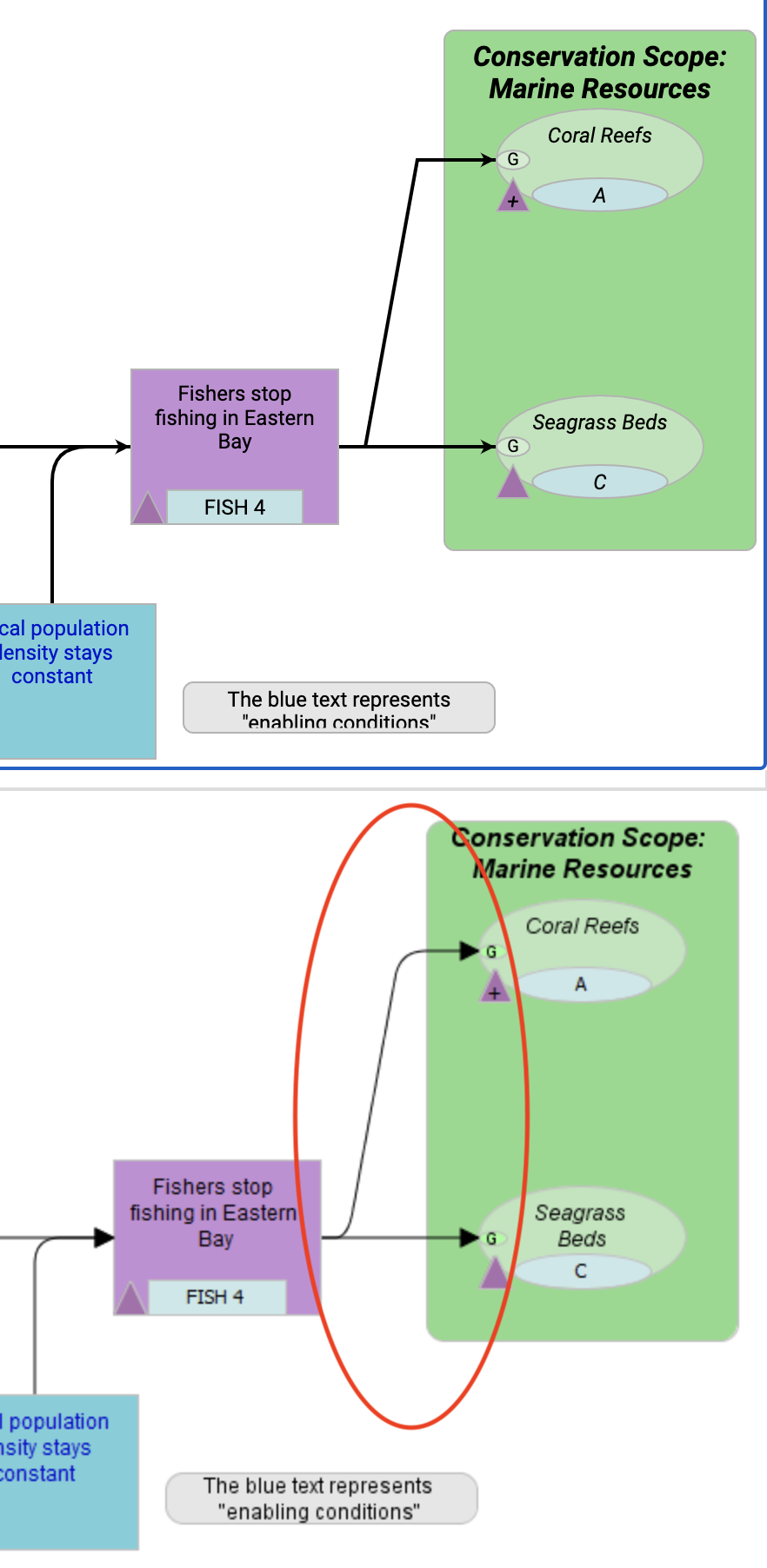
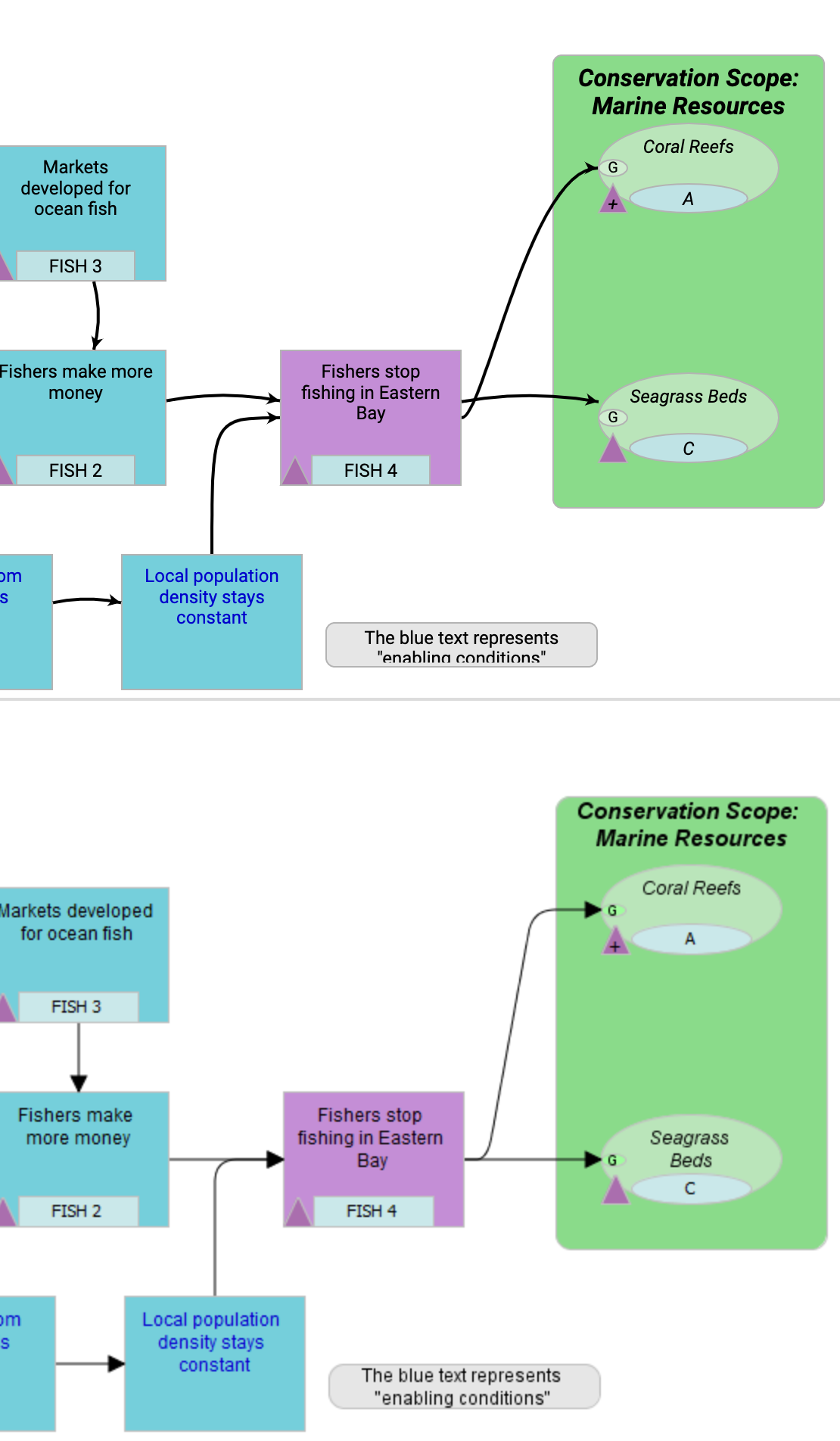
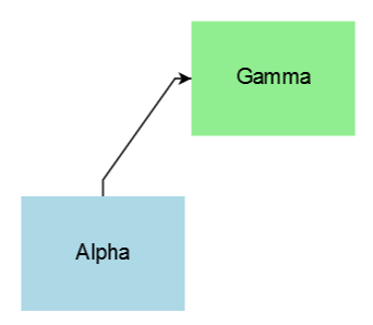
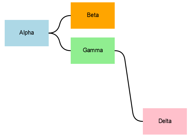
and here’s the result:

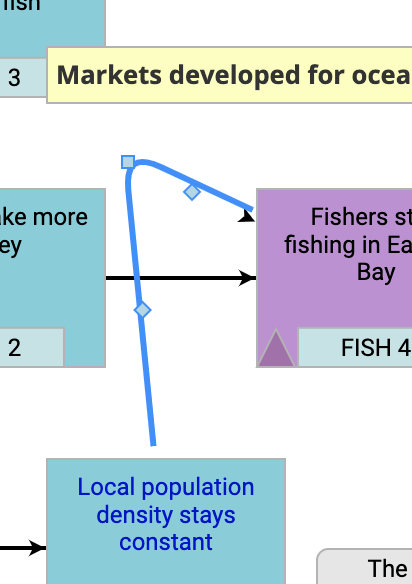
Pretty good! But now I tried moving a link point and things started getting weird (note: I only dragged the middle point of the link):

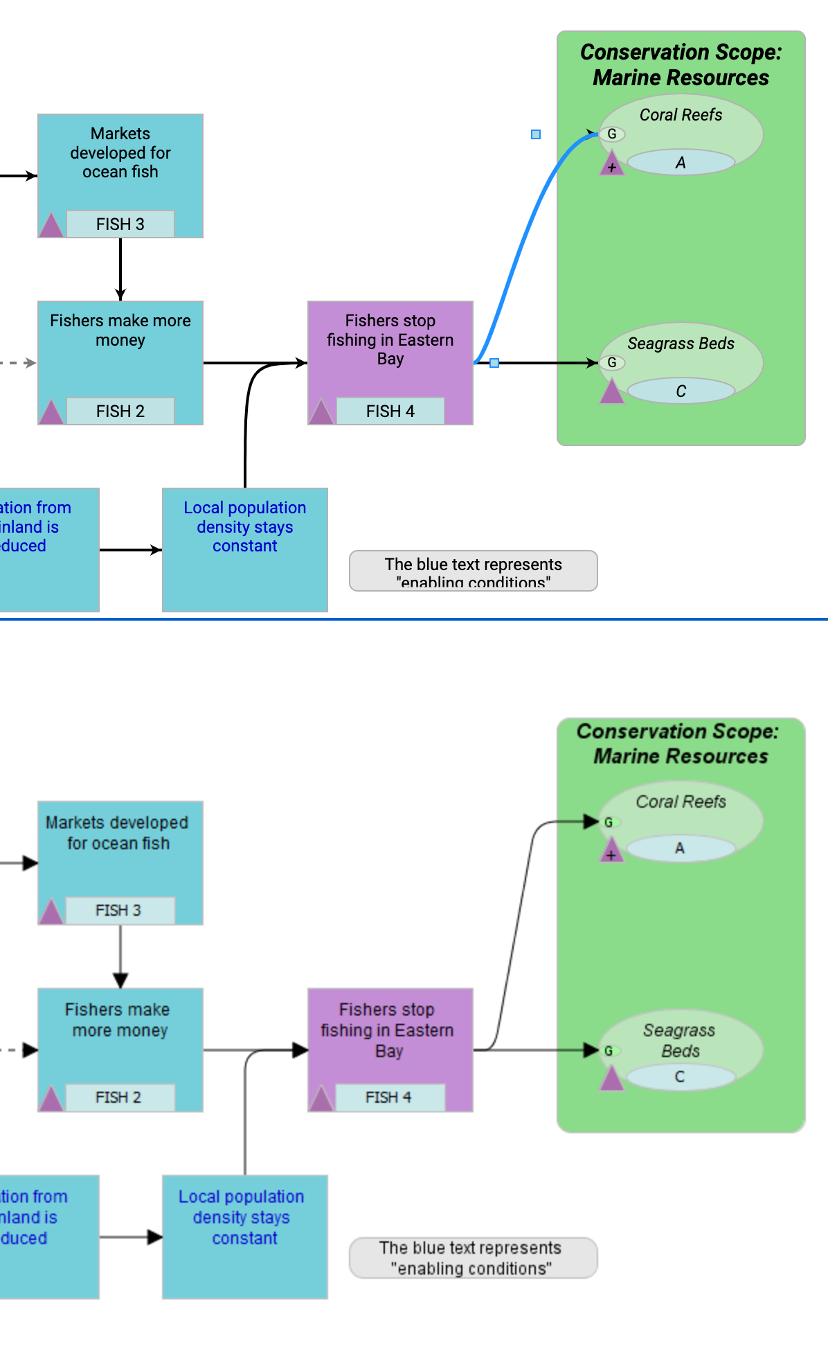
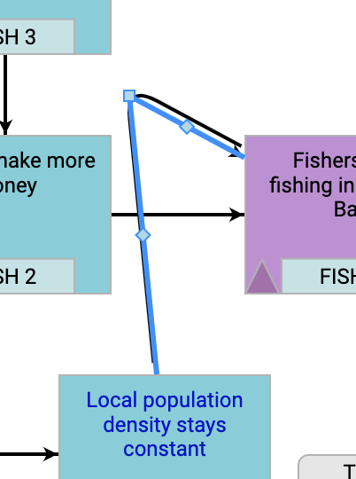
Notice that the start and end points are not where they should be…Another weird behavior I noticed, is that, if I call the super method (but just ignore the result and build my own geometry), this happens:

What other wizardries is the super method doing that affects the link selection adornment?

The reason why I didn’t follow your tip to first call the super method and then try to modify the segments is because the resulting super geometry is normalized, so the start point is 0,0, which means a whole lot of other calculations. And although we’re essentially doing the same thing (adding a line segment followed by a QuadraticBezier segment), your math to get to the points seems a bit more complicated (you have angles and rotations that I don’t quite follow…)

Any idea why the start and end points don’t land where they should?

A middle point implies that you have an odd number of points in your link route, but the code I gave you was designed to only work with the default routing that produces 4 point routes.

The code could be enhanced to account for additional points, but I just don’t have the time for that.

Yeah, I need to support any number of points. The user starts with a straight link from one node to another but then they can add as many bend points as they want. I’m not expecting you to write the code for me. But any help in guiding me in the right direction is appreciated, as you’ve been promptly providing.