Link from center spot visible inside the from node

Hello,

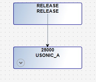
I’ve got a Problem concerning the look from a link that originates in a Center spot. As you can see in the screenshot, the link Shows up also inside the from node. I tried to stick Close to the draggable link example since I saw that this example does what I would like to have, but I have missed sth. important in the Definition of the node template, it seems.

Perhaps you have an idea what I’m doing wrong.

Thanks in advance,
Marc

Here’s the node template:

<DataTemplate x:Key="">
	<go:SpotPanel Style="{StaticResource SpotPanelStyle}"
				  go:Node.Location="{Binding Path=Data.Location, Mode=TwoWay}"
				  go:Node.LocationSpot="Center">
		<i:Interaction.Triggers>
			<i:EventTrigger EventName="MouseEnter">
				<command:EventToCommand Command="{Binding Path=DataContext.NodeMouseEnterCommand, RelativeSource={RelativeSource AncestorType={x:Type designer:GoWpfUserControl}}, Mode=OneWay}" CommandParameter="{Binding Data}"/>
			</i:EventTrigger>
			<i:EventTrigger EventName="MouseLeave">
				<command:EventToCommand Command="{Binding Path=DataContext.NodeMouseLeaveCommand, RelativeSource={RelativeSource AncestorType={x:Type designer:GoWpfUserControl}}, Mode=OneWay}" CommandParameter="{Binding Data}"/>
			</i:EventTrigger>
		</i:Interaction.Triggers>
		<go:NodePanel Background="{Binding Path=Node.IsSelected, Converter={StaticResource theSelectedBrushConverter}}">
			<Border BorderThickness="1" Padding="5,0,5,0" CornerRadius="3" BorderBrush="DarkBlue">
				<StackPanel MinWidth="100" 
							Width="150"
							MinHeight="50"
							Name="GoStackPanel"
							go:Node.PortId="" go:Node.LinkableFrom="True" go:Node.LinkableTo="True" Cursor="Hand">
					<Grid>
						<Grid.ColumnDefinitions>
							<ColumnDefinition Width="*"/>
							<ColumnDefinition Width="Auto"/>
						</Grid.ColumnDefinitions>
						<TextBlock Grid.Column="0" Grid.ColumnSpan="2" FontSize="11" FontWeight="Bold" Text="{Binding Data.Label}" TextAlignment="Center" VerticalAlignment="Center"/>
						<Image Grid.Column="1" HorizontalAlignment="Right" Width="20" Height="20" 
						   Visibility="{Binding Path=Data.IsCommissioningRelated, Converter={StaticResource BooleanToVisibilityConverter}}">
							<Image.Source>
								<BitmapImage UriSource="/MasterData/Workflow/Designer/Resources/shoppingcart.ico"/>
							</Image.Source>
						</Image>
					</Grid>
					<TextBlock FontSize="11" FontWeight="Bold" Text="{Binding Data.DescriptionWorkcentertype}" TextAlignment="Center" />
					<Expander IsExpanded="{Binding Data.IsExpanded}" Visibility="{Binding Path=Data.HasStwsAssignments, Converter={StaticResource BooleanToVisibilityConverter}}">
						<ListView ItemsSource="{Binding Data.WsdeStwsAssignments}">
							<ListView.ItemTemplate>
								<DataTemplate>
									<TextBlock FontSize="10" Text="{Binding Label}"/>
								</DataTemplate>
							</ListView.ItemTemplate>
						</ListView>
					</Expander>
				</StackPanel>
			</Border>
		</go:NodePanel>
		<!-- A Standard node has four ports, the top incoming only, the
	bottom outgoing only, and the other two support both directions.
	Port appearance depends on the Node.Tag property.
	The FromSpot and ToSpot properties control where the link connects.
	The SpotPanel properties control where the port is positioned. -->
		<!-- top -->
		<Ellipse Style="{StaticResource EllipseStyle}"
				 Stroke="{Binding Path=Data.PortsVisible, Converter={StaticResource theBooleanBrushConverter}}"
				 go:Node.PortId="PortTop"
				 go:Node.LinkableFrom="False"
				 go:Node.ToSpot="MiddleTop"
				 go:SpotPanel.Spot="MiddleTop"
				 go:SpotPanel.Alignment="MiddleTop"
				 go:Node.LinkableSelfNode="True"/>
		<!-- bottom -->
		<Ellipse Style="{StaticResource EllipseStyle}"
				 Stroke="{Binding Path=Data.PortsVisible, Converter={StaticResource theBooleanBrushConverter}}"
				 go:Node.PortId="PortBottom"
				 go:Node.LinkableTo="False"
				 go:Node.FromSpot="MiddleBottom"
				 go:SpotPanel.Spot="MiddleBottom"
				 go:SpotPanel.Alignment="MiddleBottom"
				 go:Node.LinkableSelfNode="True"/>
		<!-- left side -->
		<Ellipse Style="{StaticResource EllipseStyle}"
				 Stroke="{Binding Path=Data.PortsVisible, Converter={StaticResource theBooleanBrushConverter}}"
				 go:Node.PortId="PortLeft"
				 go:Node.FromSpot="MiddleLeft"
				 go:Node.ToSpot="MiddleLeft"
				 go:Node.FromEndSegmentLength="50"
				 go:Node.ToEndSegmentLength="50"
				 go:SpotPanel.Spot="MiddleLeft"
				 go:SpotPanel.Alignment="MiddleLeft"/>
		<!-- right side -->
		<Ellipse Style="{StaticResource EllipseStyle}"
				 Stroke="{Binding Path=Data.PortsVisible, Converter={StaticResource theBooleanBrushConverter}}"
				 go:Node.PortId="PortRight"
				 go:Node.FromSpot="MiddleRight"
				 go:Node.ToSpot="MiddleRight"
				 go:Node.FromEndSegmentLength="50"
				 go:Node.ToEndSegmentLength="50"
				 go:SpotPanel.Spot="MiddleRight"
				 go:SpotPanel.Alignment="MiddleRight"/>
	</go:SpotPanel>
</DataTemplate>

And here the screenshot:

Did you want there to be four ports (one on each side) or five ports (one on each side plus one covering almost the whole node)?

If you only want four, then you should remove the go:Node.portId="" (and the other port-related attached properties on that element). And you’ll need to make sure that every link data in the model has “from portid” and “to portid” properties.

Hi Walter,

The four ports on the side are ok and my model works well with them. But now, for playing a bit with the layout, I want to have a fifth port in the center of the node. We hope that with the “normal” route and a center port, we can better distinguish multiple links starting from the same node.
We are having Problems there in a Scenario with 4 nodes (let’s call them a, b, c, d) where a -> c, b->d but also crosswise a->d and b->c.
I added two screenshots showing my “misery”. The layout style “normal” for routes seems a bit better here than “orthogonal” or “avoidsnotes” but I fear that “normal” isn’t what we want in some other cases and are stuck to “avoidsnotes”.

normal:

avoidsnotes:

I’m thinking that you really do not want to have four ports on each node. Instead, there should only be one “port” for each node, and that should be the whole node. So you can remove all four of those port elements, and you can remove the “FromPortId” and “ToPortId” properties from the GraphLinksModel model and from the link data.

Then I would set go:Node.FromSpot="BottomSide" and go:Node.ToSpot="TopSide" on the Node template. That way the link connection points are spread out automatically along the bottom side and along the top side.

You can see such results in the Table Diagram and Piping samples, but they use “AllSides” instead of just the “BottomSide” and “TopSide”. Read the section about “Link Connection Points on Nodes” in the GoXamIntro.pdf file.

Thanks for your reply. I just tried it out. Had some Problems because after removing the spots I had no element in my node template that defined the LinkableFrom and LinkableTo attached properties. But got it to work at last.

The solution with dedicated spots for the links has the adavantage for me that I am able to differentiate what Kind of link the user is drawing, i.e. if he stats at the spots on the right or left side, I create a so called timemonitoring link. If he started at the bottom spot, I created a “normal” link. I will have a look into this if I can mix the spots on the left and right with your proposed solution of using the top and bottom sides instead of spots there.

But still I don’t see why in the draggable link example which uses a center spot it seems as if the link is not visible inside the node as it was in my example.
And what are the properties go:NodePanel.Spot1 and go:NodePanel.Spot2, which are used in the draggable link demo about? Didn’t find anything useful in the docs about them.

I suppose you could continue to use a single port element, but you would need to implement a Diagram.LinkDrawn event handler to modify the link data (or the Link directly) according to where the link-drawing operation started (Diagram.FirstMousePointInModel).

Read about the NodePanel class, for controlling where the contents (other than the first element) of the NodePanel class is positioned so that the first element can surround them.

Hi Walter,

yesterday I did some more “experiments” with mixing the bottom and top sides and specific spots on the left and right. The Problem I ran into was that then, the normal links may also be connected to the left and right side when the diagram is loaded. But from left and right spots only a specific type of link is allowed. Is there some way I could disallow this behaviour?

Kind regards,
Marc

If you want to use a single port for each node, where each port is the whole node (or maybe a little less), then you could try setting the Route.FromSpot and Route.ToSpot differently for the different kinds of links.

You can make that distinction either using separate templates or via data binding.

So now, I changed some stuff according to your last hint and got something to working.

But still, I’m not able to do sth. like the direct links in Visio when they are connected to the whole node and not to spots. If I use a center spot, the links are visible inside the nodes again as in the first screenshot I posted.
Isn’t it possible to have links which come from/point at the center spot of a node but end at the outer geometry of the node?

If the whole node acts as a “port” element (which is the default behavior, by the way), then links will do as you say: they will go towards or come in the direction of the center of the port but will actually terminate at the edge of the port.

Ah, ok. It looks better now. Thanks for your advice and patience.