Links don't spread defined ports

Hi, I’m having trouble with spreading links on defined ports.
I’m using the LayeredDigraphLayout and have set LayeredDigraphLayout.setsPortSpots to false.

Here’s the code:

function makePort(name, align, spot, output, input) {
        var horizontal =
          align.equals(go.Spot.Top) || align.equals(go.Spot.Bottom);
        return $(go.Shape, {
          fill: "transparent",
          strokeWidth: 0,
          width: horizontal ? NaN : 8,
          height: !horizontal ? NaN : 8,
          alignment: align,
          stretch: horizontal ?
            go.GraphObject.Horizontal : go.GraphObject.Vertical,
          portId: name,
          fromSpot: spot,
          fromLinkable: output,
          toSpot: spot,
          toLinkable: input,
          cursor: "pointer",
          fromLinkableDuplicates: true,
          toLinkableDuplicates: true,
          fromLinkableSelfNode: true,
          toLinkableSelfNode: true,
          mouseEnter: function (e, port) {
            if (!e.diagram.isReadOnly) port.fill = configPorts.fill;
          },
          mouseLeave: function (e, port) {
            port.fill = "transparent";
          },
        });
      }

myDiagram.nodeTemplate =
        $(
          go.Node,
          "Table",
          nodeStyle(), {
            deletable: false,
            doubleClick: (e, node) => synchronizeNewCustomer(node),
            click: (e, node) => {
              var diagram = node.diagram;
              diagram.startTransaction("highlight");
              diagram.clearHighlighteds();
              updateHighlights(node);
              diagram.commitTransaction("highlight")

            }
          },
          $(
            go.Panel,
            "Auto",
            $(
              go.Shape,
              "Rectangle", {
                fill: configNodes.fill,
                stroke: configNodes.stroke,
                strokeWidth: configNodes.strokeWidth,
                name: "NODE-SHAPE",
                isPanelMain: true
              },
              new go.Binding("fill", "color"),
              new go.Binding("stroke", "isHighlighted", function (highlighted, n) {
                return highlighted ? "orange" : "deepskyblue";
              }).ofObject()
            ),
            $(
              go.Panel,
              "Vertical",
              $(
                go.TextBlock,
                configTextStyle, {
                  margin: configNodes.margin,
                  wrap: go.TextBlock.WrapFit,
                  verticalAlignment: go.Spot.Center,
                },
                new go.Binding("text", "text")
              ),
              $(
                go.Panel,
                "Table", {
                  margin: new go.Margin(0, 20, 10, 20)
                },
                new go.Binding("itemArray", "displayInformations"), {
                  itemTemplate: $(go.Panel, "TableRow",
                    $(go.TextBlock, new go.Binding("text", "key"), {
                        column: 0,
                        margin: 4,
                        width: 130,
                        alignment: go.Spot.Left,
                        font: "bold 10.5pt Lato, Helvetica, Arial, sans-serif"
                      },
                      new go.Binding("stroke", "color")
                    ),
                    $(go.TextBlock, new go.Binding("text", "value"), {
                        column: 1,
                        alignment: go.Spot.Left
                      },
                      new go.Binding("stroke", "color")
                    )
                  )
                }
              )
            ),
          ), {
            toolTip: $("ToolTip",
              $(go.TextBlock, {
                  margin: 4
                },
                new go.Binding("text", "hint"),
                new go.Binding("visible", "hint", function (h) {
                  return h != null && h.length > 0
                })
              )
            )
          },
          // four named ports, one on each side:
          makePort("T", go.Spot.Top, go.Spot.TopSide, true, true),
          makePort("L", go.Spot.Left, go.Spot.LeftSide, true, true),
          makePort("R", go.Spot.Right, go.Spot.RightSide, true, true),
          makePort("B", go.Spot.Bottom, go.Spot.BottomSide, true, true)
        );

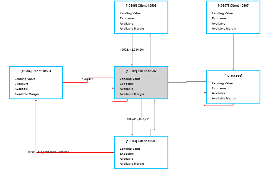
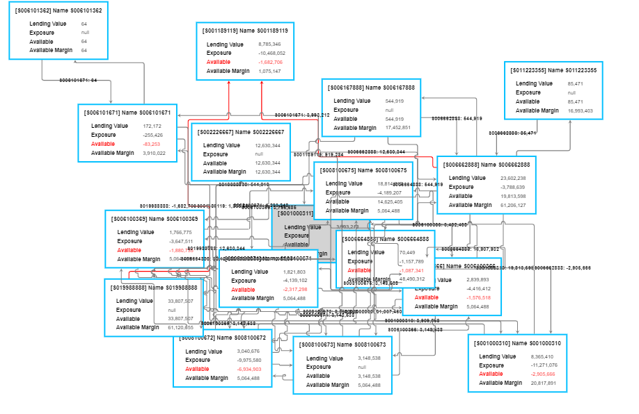
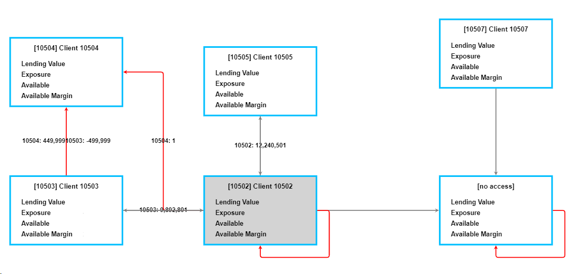
I was expecting the links to spread on the ports but they connect to the center and overlap instead.
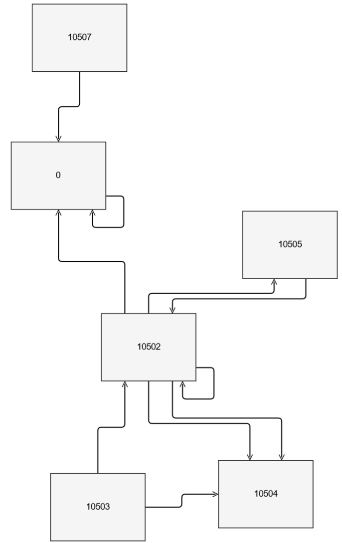
I tested the ports with test data where the fromPort and toPort properties were set and they spread just fine.

Am I missing something?

OK, I guess it’s good that you have set LayeredDigraphLayout.setsPortSpots to false. Are you expecting each link to have specific port connection information provided before any layout is done?

What is your link template? How is your model initialized? I’m wondering if you forgot to set GraphLinksModel.linkFromPortIdProperty and linkToPortIdProperty.

No, I’m not expecting any connection informatin beforehand - but there might be a possibility for the user to save the diagram model for future purposes.

Link template:

myDiagram.linkTemplate = $(
        go.Link, // the whole link panel
        {
          routing: go.Link.AvoidsNodes,
          curve: go.Link.JumpOver,
          corner: 5,
          toShortLength: 4,
          relinkableFrom: true,
          relinkableTo: true,
          reshapable: true,
          selectionAdorned: false,
        },
        new go.Binding("points").makeTwoWay(),
        $(
          go.Shape, // the link path shape
          {
            stroke: configLinks.stroke,
            strokeWidth: configLinks.strokeWidth,
            name: "LINK-SHAPE",
          },
          new go.Binding("stroke", "isHighlighted", function (highlighted, l) {
            return highlighted ? "orange" : l.part.data.color;
          }).ofObject()
        ),
        $(go.TextBlock,
          {font: "bold 10pt sans-serif"},
          new go.Binding("text", "text"),
          new go.Binding("visible", "text", function (text) {
            return text && text != "null";
          })),
        $(
          go.Shape, // the arrowhead
          {
            toArrow: "standard",
            strokeWidth: 0,
            name: "ARROWHEAD"
          },
          new go.Binding("fill", "isHighlighted", function (highlighted, l) {
            return highlighted ? "orange" : l.part.data.color;
          }).ofObject(),
          new go.Binding("stroke", "isHighlighted", function (highlighted, l) {
            return highlighted ? "orange" : l.part.data.color;
          }).ofObject(),
        )
      );

Model initialization:

var myModel = $(go.GraphLinksModel);
        myDiagram.layout = $(go.LayeredDigraphLayout, {
          direction: 90,
          layeringOption: go.LayeredDigraphLayout.LayerLongestPathSource,
          setsPortSpots: false,
        });
        myModel.linkKeyProperty = "key";
        myModel.nodeDataArray = nodeData;
        myModel.linkDataArray = nodeLinksData;
        myModel.linkFromPortIdProperty = "fromPort";
        myModel.linkToPortIdProperty = "toPort";
        myDiagram.model = myModel;
        this.jsonModel = myDiagram.model.toJson();

In your screenshot it appears that some of the overlapping link segments are due to reflexive links (i.e. link.fromNode === link.toNode). Normally reflexive links do not participate with the spread connections of links with “Side…” spots. But you might want to do something like:

  function updateLinkSpots(link, oldport, newport) {
    if (link.fromNode !== null && link.fromNode === link.toNode) {
      link.fromSpot = new go.Spot(1, 0.999, 0, -10);
      link.toSpot = new go.Spot(0.999, 1, -10, 0);
    } else {
      link.fromSpot = go.Spot.Default;
      link.toSpot = go.Spot.Default;
    }
  }

  myDiagram.linkTemplate =
    $(go.Link,
      {
        routing: go.Link.AvoidsNodes,
        curve: go.Link.JumpOver,
        corner: 5,
        toShortLength: 4,
        relinkableFrom: true,
        relinkableTo: true,
        reshapable: true,
        selectionAdorned: false,
        fromPortChanged: updateLinkSpots,
        toPortChanged: updateLinkSpots
      },
      . . .

Adapt the code so that it assigns the fromSpot and toSpot that you want for your reflexive links.

I’m having trouble finding the offset where it’s trying to connect to. Is it possible to find the relative offset for me to deduct what port it should be?

Your Nodes have distinct ports, whereas the code I provided ignores those ports for reflexive Links. Sorry about that.

If you really want reflexive links to connect with the individual ports of the node, you’ll need to make your code smarter to take the Link.fromPort and Link.toPort into account when computing the Link.fromSpot and Link.toSpot.

Maybe I need to rephrase the main issue:
Maybe it wasn’t very noticeable in the first screenshot. But all the arrows overlap and connect to the same spot instead of the port.
The ports I have defined are being ignored in any case on initial layout. I tried to loop over all connections and update their spots/ports but it’s not possible as they all have the default spot set - which means they all return the same offset and values.

How do can I achieve that the connections use the actual ports instead of the default spot?
Else the entire layouting would be not useful at all.

Here’s an example. I want to go from this:

to this:

It’s odd, because what you describe as what you want is the normal behavior. Other than the routing of reflexive links, which is independent of the routing of inter-node links.

Yes, some Layouts will override some link fromSpot and toSpot values, but you have already disabled that in your Diagram.layout.

One thing that you should try is to set all of the model properties before setting the Model.nodeDataArray and GraphLinksModel.linkDataArray.

I have tried that and am getting the same result as before.

I’ll see if I can reproduce your example. I’ll ignore all of the details within the nodes, since they don’t matter for this issue. The link labels and all of the colors don’t matter either.

Additional questions:

Why do you want to use multiple ports? Is that needed? Do you expect the layout to produce different locations for the nodes depending on which links connect to which sides of the nodes?

The latter is not what any of the layouts do.

Here is the code that I’m trying for you. It does not use ports.

<!DOCTYPE html>
<html>
<head>
  <title>Minimal GoJS Sample</title>
  <!-- Copyright 1998-2022 by Northwoods Software Corporation. -->
</head>
<body>
  <div id="myDiagramDiv" style="border: solid 1px black; width:100%; height:800px"></div>
  <script src="https://unpkg.com/gojs"></script>
  <script id="code">
function init() {
  const $ = go.GraphObject.make;

  myDiagram =
    $(go.Diagram, "myDiagramDiv",
      {
        layout: $(go.ForceDirectedLayout, {  })
      });

  myDiagram.nodeTemplate =
    $(go.Node, "Auto",
      { width: 140, height: 100 },
      { fromSpot: go.Spot.AllSides, toSpot: go.Spot.AllSides },
      $(go.Shape, "Rectangle", { fill: "whitesmoke" }),
      $(go.TextBlock, new go.Binding("text", "key")),
    );

  function updateLinkSpots(link, oldport, newport) {
    if (link.fromNode !== null && link.fromNode === link.toNode) {
      link.fromSpot = new go.Spot(1, 0.999, 0, -20);
      link.toSpot = new go.Spot(0.999, 1, -20, 0);
    } else {
      link.fromSpot = go.Spot.Default;
      link.toSpot = go.Spot.Default;
    }
  }

  myDiagram.linkTemplate =
    $(go.Link,
      {
        routing: go.Link.AvoidsNodes,
        curve: go.Link.JumpOver,
        corner: 5,
        toShortLength: 4,
        relinkableFrom: true,
        relinkableTo: true,
        reshapable: true,
        selectionAdorned: false,
        fromPortChanged: updateLinkSpots,
        toPortChanged: updateLinkSpots
      },
      new go.Binding("points").makeTwoWay(),
      $(go.Shape, { strokeWidth: 1.5 }),
      $(go.Shape, { toArrow: "OpenTriangle" })
    );

  myDiagram.model = $(go.GraphLinksModel,
  {
    nodeDataArray: [
      { key: 10505 },
      { key: 10507 },
      { key: 10504 },
      { key: 10502 },
      { key: 0 },
      { key: 10503 },
    ],
    linkDataArray: [
      { from: 10505, to: 10502 },
      { from: 10502, to: 10505 },
      { from: 10507, to: 0 },
      { from: 10502, to: 10504 },
      { from: 10502, to: 10502 },
      { from: 10502, to: 0 },
      { from: 0, to: 0 },
      { from: 10503, to: 10504 },
      { from: 10503, to: 10502 },
      { from: 10502, to: 10504 },
    ]
  });
}
window.addEventListener('DOMContentLoaded', init);
  </script>
</body>
</html>

produces this diagram:

No multiple ports are needed. I used an example from your templates (I thought it was necessary to allow the links to connect on all sides with spreading).

Your example looks good. Is it possible to use layering algorithms like LayeredDigraphLayout? This is impossible to use with many nodes and connections:

Thank you for your time! Very appreciated.

If you are going to use ForceDirectedLayout, you’ll want to increase the defaultSpringLength property to account for the large and more numerous nodes. Maybe also increase the defaultElectricalCharge.

But you are right that ForceDirectedLayout really doesn’t work well when the graph is not close to planar, due to too many links. Here is an experimental layout: Grid Channel Routing But I don’t know your problem domain, so I cannot guess whether that sample is of use to you.