i’m having a problem with the way links are drawn after i added ports around a node.
A node in our application has ports all around it’s side, and the user can drag a link end to another port.
I’ll add some screenshots to show how the links are drawn
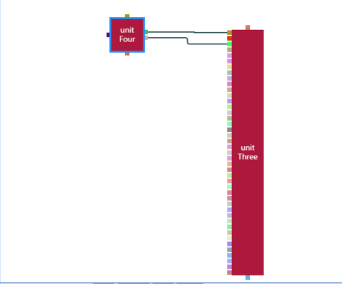
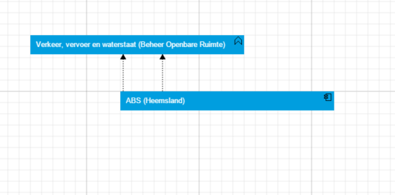
In this case the link.Routing is set to default
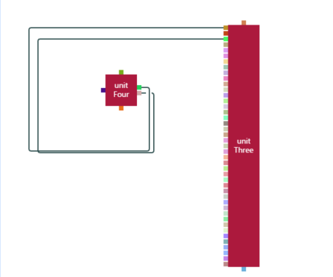
here its set to Orthogonal
if the ports are directly below eachother, the problem does not occur with the link.Routing set to default
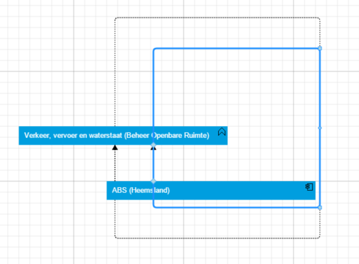
but if its set to Orthogonal it looks like this *
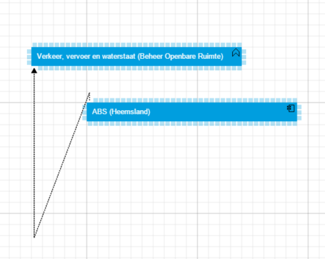
Since i got the implementation ideas from the dynamic ports example, i looked at the example to see if a similar problem occured, and it does… (but in a lesser extent)
again the links make a large detour to get from their starting point to their end point
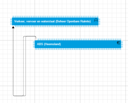
but if the ports are on the same axis it gets drawn correctly
If you don’t mind my asking, why do you have so many ports? Do you really need to have so many logically distinct connection elements?
Or do you just want to control where links connect on the node? If this latter situation is the case, there are many simpler alternatives to what you are doing.
Having that many ports is not necessary, in essence we want to control where the links connect. But from a visual perspective we like the way this looks (this ports appear when the relinkingtool activates and disappear when it deactivates).
So no, we don’t absolutely need all the ports, but we’d rather use it like this.
One possible implementation strategy would be to set the Link.fromSpot and Link.toSpot to control where the link connects with the node. Take a look at Link Shifting Tool, demonstrating the LinkShiftingTool, which supports the user’s interactively shifting the connection point for a link.
With the situation as it is, I think you could explicitly set the GraphObject.fromEndSegmentLength and toEndSegmentLength to be a small fixed value, such as 10, on each of the port objects in your nodes. Hmmm, maybe you could just stop using the custom Link class that the Dynamic Ports sample uses.
 *
*