MakeBitmap results in missing/wrong Nodes

Hello,

After creating a Diagram, MakeBitmap is called on the following diagram:

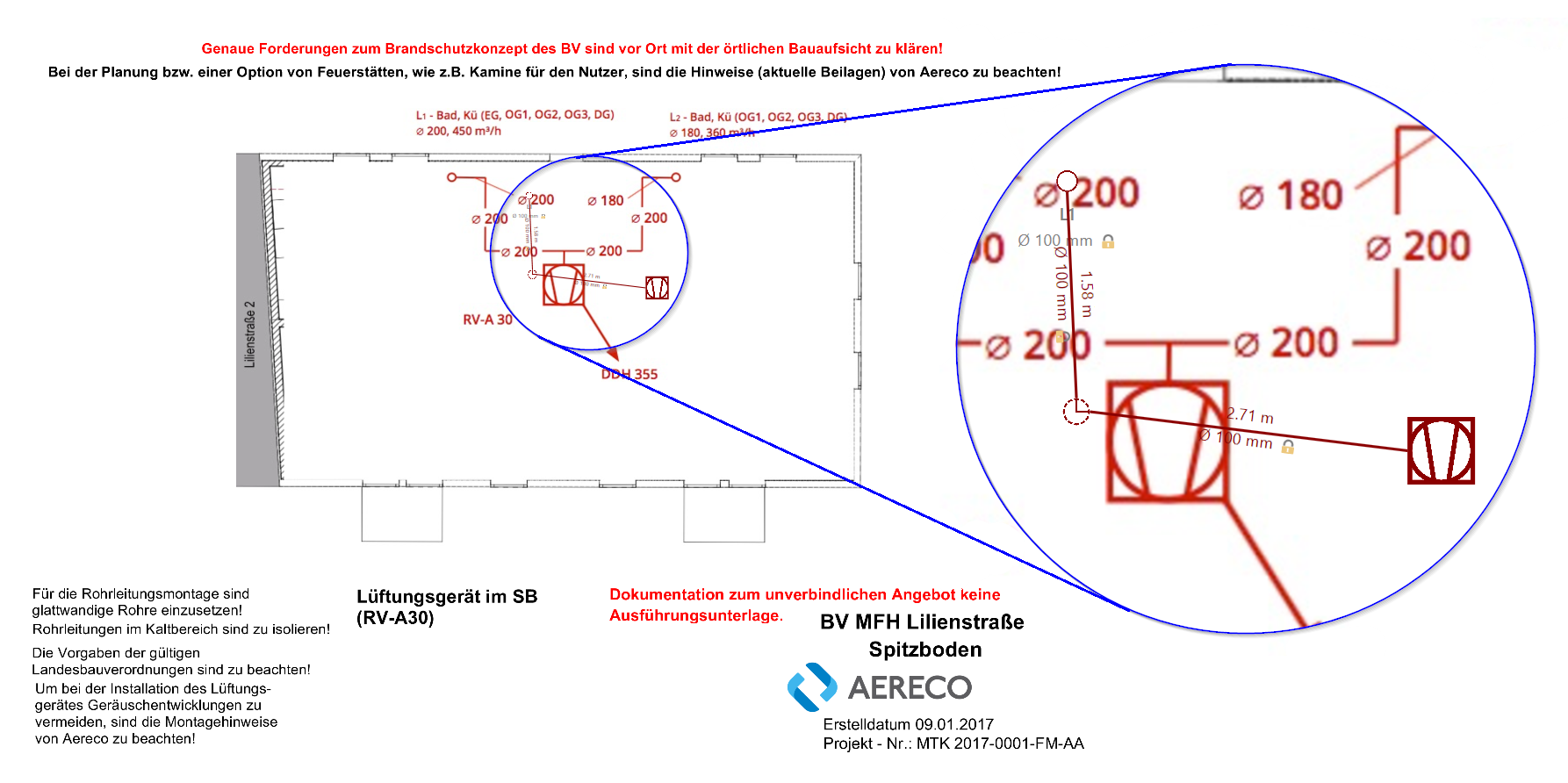
This is actually a node, whose template contains a large background image:

<DataTemplate x:Key="BackgroundNodeTemplate">
    <go:NodePanel go:Part.LayerName="{Binding Path=Data.Layer.Id}"
                  go:Node.Location="{Binding Path=Data.Location, Mode=TwoWay}"
                  IsHitTestVisible="False"
                  go:Part.Visible="{Binding Path=Data.IsVisible}"
                  go:Node.RotationAngle="{Binding Path=Data.Angle}">
        <Image Source="{Binding Path=Data.GroundPlanImagePath}"
               Width="{Binding Path=Data.Width}"
               Height="{Binding Path=Data.Height}" />
    </go:NodePanel>
</DataTemplate>

with three nodes of the same type and two links of the same type atop:

<DataTemplate x:Key="ComponentNodeTemplate">
    <StackPanel Style="{StaticResource StatusStackPanelStyle}"
                go:Part.SelectionElementName="VisualComponent"
                go:Part.Rotatable="True"
                go:Part.Visible="{Binding Path=Data.IsVisible}"
                go:Node.Location="{Binding Path=Data.Location, Mode=TwoWay}"
                go:Part.LayerName="{Binding Path=Data.Layer.Id}"
                go:Part.RotateAdornmentTemplate="{StaticResource RotationAdornmentTemplate}"
                go:Node.RotationAngle="{Binding Path=Data.Angle, Mode=TwoWay}"
                go:Node.LocationSpot="Center">
            
        <go:SpotPanel Width="Auto"
                      HorizontalAlignment="Center"
                      go:Part.SelectionAdorned="False"
                      MouseLeftButtonDown="Node_MouseLeftButtonDown"
                      MouseEnter="Node_MouseEnterComponent"
                      MouseLeave="Node_MouseLeaveComponent"
                      Name="VisualComponent">
            <go:NodePanel Sizing="Auto"
                          go:Node.PortId="Component"
                          go:SpotPanel.Main="True">
                <StackPanel>
                    <Grid Width="{Binding Path=Data.IconSize.Width}"
                          Height="{Binding Path=Data.IconSize.Height}">
                        <Grid.RowDefinitions>
                            <RowDefinition />
                            <RowDefinition Height="Auto" />
                        </Grid.RowDefinitions>
                        <Image Source="{Binding Path=Data.Icon}"
                               Stretch="UniformToFill"
                               HorizontalAlignment="Center"
                               VerticalAlignment="Center"></Image>
                    </Grid>
                </StackPanel>

            </go:NodePanel>
            <!-- some ports -->
            ...

        </go:SpotPanel>
        <TextBlock Text="{Binding Path=Data.Text}"
                   HorizontalAlignment="Center"
                   FontSize="13"
                   FontWeight="DemiBold"
                   Style="{StaticResource StatusNodeTextStyle}" />
        <!-- Optional diameter text -->
        <StackPanel>
            ...
        </StackPanel>
    </StackPanel>
</DataTemplate>

As you can see, those are actually just a background icon with some ports and optional text (you can see that on the top node - the name “L1” and the diameter of the pipe)

As the links are drawn correctly I consider them irrelevant and leave them out here. They’re not much more than a LinkShape with a TextBlock for the length and a text part for the diameter same as for the node.

Now, when MakeBitmap is called the result looks like this:

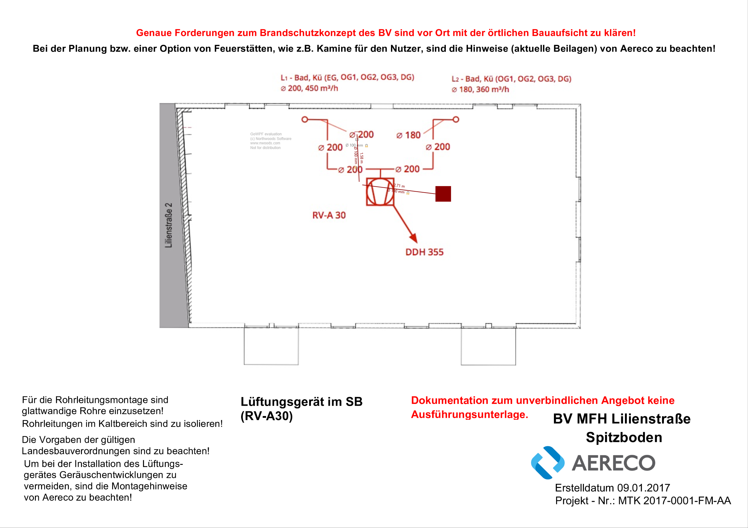
Some background icons are incorrect and some not visible at all. We do have a node looking like the red square in the right node but the middle one is not visible and the top one is a horizontal line that could be part of another image (we don’t have such an icon, though). Also there are other nodes in the diagram, which are invisible at the moment the image is created (some of them use the red square). How is it possible the images are changed upon creating the BitmapImage?

So the only problem seems to be that some Images are rendering the wrong image file during MakeBitmap? That is very surprising. I have never heard of such behavior and I cannot explain it. I can review our code and search the web for any similar behaviors.

Yes, that seems to be the problem. I’m not sure whether gets the wrong image path of the visible nodes or tries to read the image path from a hidden node, though.

Just had another look at the nodes and layers, all the layers are visible but the nodes have Visibility and IsVisible set correctly. Only the ones that are supposed to be displayed have Visibility set to Visible and IsVisible to true, the others have Visibility set to Collapsed and IsVisible to false

First, I should ask exactly which platform you are targeting.

Second, are you saying that you have multiple Nodes at the same locations, and that some are supposed to be visible and some are not? So you are suspecting that some non-visible Nodes are being drawn when they should not be? And those that should not be drawn but are drawn are in front of those that you were hoping to be visible in the rendered bitmap?

Oh, third, did you mean the Part.Visible boolean property? There is no “IsVisible” property.

.NET 4.5.2

No, the other invisible nodes are actually at a different location. I just thought it possible the method is asking the wrong node for the image URI. Then again, why wouldn’t it ask the wrong node for the location. I don’t know, it was just an idea.

In your screenshots, there is only one node that normally renders correctly but that appears as a solid brown square in the bitmap, yes?

And that node is actually implemented with an Image element? How is that template declared? And how is that template different from the node on the left that seems to show the same figure slightly larger and more reddish color?

Here is a recolored version of the diagram. Everything in green is actual nodes or links. The grey text below the top node is part of the node, and the text alongside the green links are part of the corresponding links. The rest in the lighter red is just part of the background image. I suppose our customer used an existing plan drawn by hand and loaded it into our program to actually recreate the plan with our software, but those are not individual nodes or links.

All the (here tinted green) nodes are rendered incorrectly, that is, with the wrong image or with no image at all.

Thanks for recoloring to show what is what, and thus what is rendering incorrectly in the bitmap. I definitely missed the fact that the two small circle nodes were not rendered either.

Anyway, back to what I was asking for – how are those nodes defined in XAML?

I’ve included the XAML in the original post. Take a look at the second piece of code, the one that starts with

<DataTemplate x:Key="ComponentNodeTemplate">

All of the three nodes use this template.

I was curious what StatusStackPanelStyle does. But now that I’m looking more carefully at the DataTemplate, I see a potential problem.

Why does the NodePanel include a StackPanel with only one element in it? NodePanel should have two or more elements – the main element is the one that will act as a border around the other element(s).

As far as I remember there was an issue with centering the node when text is displayed, but it is months ago and I actually can’t see how that issue could have been fixed by the way the template is defined. But even if I stripped off the seemingly irrelevant elements, there would still only be the <image> left in the NodePanel as there is nothing more to the node itself. The text elements are defined and displayed outside of it and that is desired, they should not change port positions or anything on the node.

StatusStackPanelStyle defines the Node as selectable depending on the property status, which is a simple enum with the four states you can see here. There is an additional fifth state but hasn’t been considered here.

<Style x:Key="StatusStackPanelStyle" TargetType="StackPanel">
    <Style.Triggers>
        <DataTrigger Binding="{Binding Path=Data.Status}" Value="{x:Static style:PartStatus.Default}">
            <Setter Property="go:Part.Selectable" Value="{Binding Path=Data.IsSelectable}" />
        </DataTrigger>
        <DataTrigger Binding="{Binding Path=Data.Status}" Value="{x:Static style:PartStatus.Selected}">
            <Setter Property="go:Part.Selectable" Value="{Binding Path=Data.IsSelectable}" />
        </DataTrigger>
        <DataTrigger Binding="{Binding Path=Data.Status}" Value="{x:Static style:PartStatus.Disabled}">
            <Setter Property="go:Part.Selectable" Value="False" />
        </DataTrigger>
        <DataTrigger Binding="{Binding Path=Data.Status}" Value="{x:Static style:PartStatus.Unselectable}">
            <Setter Property="go:Part.Selectable" Value="False" />
        </DataTrigger>
    </Style.Triggers>
</Style>

If you simplify the DataTemplate to avoid this problem with NodePanel, does the bitmap still render incorrectly?

If it’s still a problem, I’m starting to run out of ideas. DiagramPanel.MakeBitmap doesn’t really do anything to the Nodes and Links, so I do not see anything that would explain the behavior you are seeing. And I’ve never seen such problems before.

Which leads me to ask if you have this problem on other machines.

Yes, this problem exists on other machines, too.

I’ve stripped the template off of pretty much everything but the image, yet the problem persists.

<DataTemplate x:Key="ComponentNodeData">
    <Image Width="{Binding Path=Data.IconSize.Width}"
           Height="{Binding Path=Data.IconSize.Height}"
           Source="{Binding Path=Data.Icon}"

           go:Part.Visible="{Binding Path=Data.IsVisible}"
           go:Part.LayerName="{Binding Path=Data.Layer.Id}"
           go:Node.Location="{Binding Path=Data.Location, Mode=TwoWay}" />
</DataTemplate>

The Icon property was actually a BitmapImage, which I’ve just changed to a URI string to see if that might cause the problem but even with a path to an image set as Source the problem still persists

Can you characterize which Images are not rendered in the resulting bitmap? Do they all disappear, or just a subset of them? If the latter case, can you tell which ones? Are they all visible on-screen before and after calling MakeBitmap? Where are the images actually located? Does the LayerName matter? Which Layers are those nodes in?

Is there a way for you to check that the Image Width, Height, Source, and Node.Visible, .LayerName, and .Location all have legitimate values?

There are three images used for the nodes, visible in the Diagram:

I don’t know what is happening to the first one, but there is a horizontal line drawn in the image. The second one disappears altogether and instead of the third one, the following is rendered:

We have a class serving the images as cache:

public sealed class DiagramHandler {
    private readonly IDictionary<string, BitmapImage> _images;
    public IReadOnlyDictionary<string, BitmapImage> Images => this._images as IReadOnlyDictionary<string, BitmapImage>
    
    private DiagramHandler() {
        this._images = new Dictionary<string, BitmapImage>();

        foreach (string imagePath in Directory.GetFiles(Path.Combine(Directory.GetCurrentDirectory(), "RibbonImages"))) {
            try
            {
                BitmapImage image = new BitmapImage();
                image.BeginInit();
                image.UriSource = new Uri(imagePath);
                image.EndInit();
                this._images.Add(Path.GetFileName(imagePath), image);
            }
            catch (Exception)
            {
                // This makes sure that the files in the images folder, which cannot be converted to bitmap are ignored
            }
        }
    }

    private static DiagramHandler _instance;
    public static DiagramHandler Instance
    {
        get
        {
            if (_instance == null)
            {
                _instance = new DiagramHandler();
                _instance.InitializePalettes();
            }
            return _instance;
        }
    }

    ...
}

As you can see the images are loaded from the current directory, which would be the project’s bin\Debug directory in my case into the cache as BitmapImage. They’re loaded in the node data when the icon name or status is set (to every status, there’s a different image).

public abstract class AstaNodeData : GraphLinksModelNodeData<string> {
    private PartStatus _status;
    public PartStatus Status
    {
        get { return this._status; }
        set
        {
            PartStatus oldStyle = this._status;
            this._status = value;
            this.IconName = this.IconName;
            RaisePropertyChanged("Status", oldStyle, value);
        }
    }

    private string _iconName;
    public string IconName
    {
        get { return this._iconName; }
        set
        {
            string stateIconName = $"{Path.GetFileNameWithoutExtension(value)}_{this.Status.ToString("F").ToLowerInvariant()}.png";

            BitmapImage icon;
            if (value != null && (DiagramHandler.Instance.Images.TryGetValue(stateIconName, out icon) || DiagramHandler.Instance.Images.TryGetValue($"{Path.GetFileNameWithoutExtension(value)}_default.png", out icon)))
            {
                BitmapImage oldIcon = this.Icon;
                this.Icon = icon;
                RaisePropertyChanged("Icon", oldIcon, icon);
            }
            this._iconName = value;
        }
    }

    public BitmapImage Icon { get; private set; }

    ...
}

Yes, all the images are perfectly visible before the call to MakeBitmap. MakeBitmap is called in the OnNavigatedFrom method, so I cannot confirm whether they’re visible immediately afterwards as they get blended out but when I navigate back, they’re visible again. Well, the LayerName assigns the Node to a certain layer. In this case, all three elements are on the same layer. Only the elements on a certain layer are visible.

Just checked the Nodes before the call to MakeBitmap. The Node itself’s width and height are set to NaN, while ActualHeight and ActualWidth are set correctly. The IconSize in Node.Data is set correctly. Location and Visibility are also set correctly both in the Node as well as in the Node.Data.

Hmmm, I don’t see any other potential problems in your code that would explain missing images when rendering to a bitmap, as long as they appeared correctly onscreen.

Just to check, I tried adding this code to a sample for which I do not remember ever trying to call DiagramPanel.MakeBitmap, the Beat Paths sample.

    private void Button_Click(object sender, System.Windows.RoutedEventArgs e) {
      Rect bounds = myDiagram.Panel.DiagramBounds;
      double w = bounds.Width;
      double h = bounds.Height;
      double s = 1.0;
      myDiagram.Panel.MakeBitmap(new Size(w, h), 96, new Point(bounds.X, bounds.Y), s,
        bmp => {
          PngBitmapEncoder png = new PngBitmapEncoder();
          png.Frames.Add(BitmapFrame.Create(bmp));
          using (System.IO.Stream stream = System.IO.File.Create(@"C:\temp\WPFbitmap.png")) {
            png.Save(stream);
          }
        });
    }

Of course this worked, as expected.