Hi,
I have a requirement that I should be able to mirror the node along x axis or y axis. Also that the port should be at the corresponding place after the mirroring.
Does goxam has any feature to mirror the node ?
Hi,
I have a requirement that I should be able to mirror the node along x axis or y axis. Also that the port should be at the corresponding place after the mirroring.
Does goxam has any feature to mirror the node ?
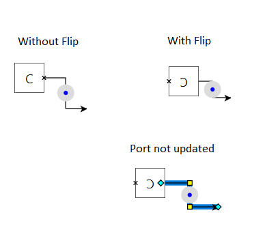
Programmers normally do not want to flip a node along either the vertical or horizontal axis because that would flip the text that the node is displaying.
So you will want to flip, using a standard transform each Shape, rearranging the panels so that the ports are moved and flipped appropriately, including flipping the FromSpot and ToSpot as needed.
I would also want the text also to be flipped along with the node shape
Does it work in your templates to apply the transform to the whole node if you also flip the FromSpot and ToSpot on each port?
Yes. I tried to use the render transform to the templates on flip command but the problem is that the adornments are not staying on the shapes anymore. It goes to right side of the node and not at all on the node.
Which Adornments? A small screenshot would help.
Consider the following images
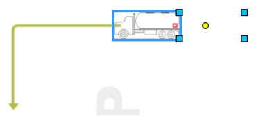
Before Mirror: If you check the blue dots its well around my node
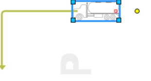
After Mirror: But after I flip the node moved to left but the blue dots are the same
It looks as if you need to transform the element(s) about the middle of the object.
Tried RenderTransform and LayoutTransform above issue with blue dots occurs
Could you show us the node template? You can strip out all of the irrelevant details – what’s the minimum template that (almost) does what you want?
Please refer the below image.
After applying the scalarTranform to the whole DataTemplate, adorment issue is resolved.
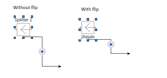
The position of the ports in the UI is updated, but when creating a link, the starting point of the link still points to the older position of the port.
I understand this could be solved with the help of the SpotPanel, but is there any other way to resolve this issue.
Since we have completed the design of our shapes, we prefer not to change it.
Below is a sample data template’s design for your reference.
    <DataTemplate x:Key="{x:Static prop:Resources.SplitterTemplate}">
        <StackPanel Tag="Splitter" go:Node.Location="{Binding Path=Data.Location, Mode=TwoWay}"
                        Name="Container"
                        go:Node.LocationSpot="Center"
                        go:Node.SelectionElementName="ItemData"
                        go:Node.Resizable="True" go:Node.ZOrder="1">

            <Grid Name="ItemData" MinHeight="58" MinWidth="45" Background="Transparent" RenderTransform="{Binding Path=go:Node.RenderTransform}">
                <Grid.RowDefinitions>
                    <RowDefinition Height="18"/>
                    <RowDefinition Height="*"/>
                    <RowDefinition Height="5"/>
                </Grid.RowDefinitions>
                <Grid.ColumnDefinitions>
                    <ColumnDefinition Width="5"/>
                    <ColumnDefinition Width="*"/>
                    <ColumnDefinition Width="5"/>
                </Grid.ColumnDefinitions>
                <TextBlock Grid.ColumnSpan="3" Text="{Binding Path=Data.Key}" HorizontalAlignment="Center"/>
                <!--Port definition-->
                <local:MandatoryPort go:Node.LinkableFrom="True" go:Node.LinkableTo="True" Grid.Row="1" Grid.Column="0" go:Node.PortId="OutPort1" HorizontalAlignment="Right"/>
                <local:MandatoryPort go:Node.LinkableFrom="True" go:Node.LinkableTo="True" Grid.Row="1" Grid.Column="2" x:Name="InPort1"  HorizontalAlignment="Left" go:Node.PortId="InPort1" />
                <local:MandatoryPort go:Node.LinkableFrom="True" go:Node.LinkableTo="True" Grid.Row="2" Grid.Column="1" x:Name="OutPort2"  HorizontalAlignment="Center" VerticalAlignment="Top" go:Node.PortId="OutPort2" />

                <Grid Name="Shape" Grid.Row="1" Grid.Column="1" MinHeight="35" MinWidth="35" >
                    <Grid.ColumnDefinitions>
                        <ColumnDefinition Width="*"/>
                        <ColumnDefinition Width="*"/>
                    </Grid.ColumnDefinitions>
                    <Rectangle Grid.ColumnSpan="2" Stroke="Gray" StrokeThickness="1"
                               Cursor="Hand" MinHeight="35" MinWidth="35" Fill="White"/>
                    <Rectangle Grid.Row="1" Grid.ColumnSpan="2" Height="0" Width="0" go:Node.LinkableTo="True" go:Node.PortId="OptPort1"/>
                    <Path Grid.Column="1" Margin="0,5,0,5" Stretch="Fill" Stroke="Gray" Data="M 15 4 L 0 4 M 8 8 L 0 4 L 8 0" />
                </Grid>
            </Grid>
        </StackPanel>
</DataTemplate>RenderTransform necessarily only transforms what is drawn. It does not actually move any of the elements. So the port remains at the bottom of the node.
You’ll need to move the port to be where you want it to be.
I suppose you could try using a LayoutTransform instead, but I’m not confident that is a magic solution.
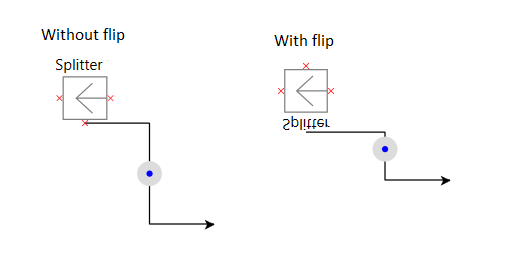
I tried the transformations but the issue still persists and I am not able to achieve the functionality.
As you can see, the port position of the shape is updated on the UI after the transformations are applied on it. But the link still points to the previous port location. I’m guessing this is because the LinkableTo/LinkableFrom is unaware of the transformation happened on the shape? or is there any other reason for it ?
If you move either node, does the link route “fix” itself?
If it does, then after changing the LayoutTransform you could call Part.InvalidateRelationships.
If it does not, then the known position of the port has not changed. You might need to flip the icon and move the ports yourself.
The link route does not fix itself.
How can I move the ports ? Visually, on the UI the ports are moved. How to move them in goXam level?
I’ll try this out later today.
So, I started from the Dynamic Ports sample. Basically, I just added this to the Node template:
        <FrameworkElement.LayoutTransform>
          <ScaleTransform ScaleY="1" ScaleX="-1" />
        </FrameworkElement.LayoutTransform>
That produces:
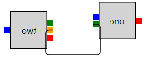
So I was wrong – the routing of the links does know the new reversed positions of the ports, but it does not know that the directions and spots need to be reversed.
If I change the ToSpot and FromSpot to be:
go:Node.LinkableTo="True" go:Node.ToSpot="MiddleRight">
and
go:Node.LinkableFrom="True" go:Node.FromSpot="MiddleLeft">
then the results are:
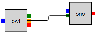
Now the routing direction is right, but the connection point is wrong, because the assumption is now wrong that the FromSpot or ToSpot provides both the connection point and the direction for the end segment of any link connecting with the port.
In this particular case it’s easiest to just set the Route.FromShortLength and Route.ToShortLength in the Link template to be the width of the port:
          <go:Route Routing="Orthogonal" Corner="4" Curve="JumpOver"
                    FromShortLength="8" ToShortLength="8"
                    RelinkableFrom="True" RelinkableTo="True" />
thereby achieving:
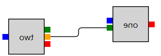
But this is not a generally applicable solution.