We are using GraphLinksModelNodeData/GraphLinksModelLinkData for some block diagraming.
Our diagrams are more static than editable by the end user, but we use the edition to layout them easily.
We are creating nodes with ports at specific position and we link to these ports.
As a result, we want a nice diagram with straight and orthogonal links.
We are struggling a bit to have the links straight from one block to the other - without any step.
We didn’t pay too much attention on the layout of our nodes and port placement.
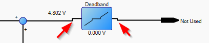
So, if you have a link from one node to another, you have a link with a step up to the next node, you move the next node down by 1 grid snap, and then you have a step down in the link.
My understanding is that we probably have to design our nodes to have their port right on the grid ?
Do you have any document giving strong guidelines how to create a coherent library of nodes (symbols) ?
I mean that you can move the node/symbol anywhere reaching straight links in without steps.
Could you show a few small screenshots demonstrating the situations you are concerned about?
Perhaps you don’t need or want separate ports on your nodes? Then links could route straight when a straight line would connect, and make a turn or two if not, in order to maintain orthogonality.
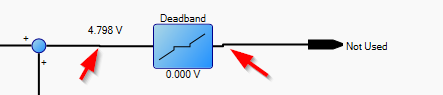
None is perfectly aligned, because my ports are not aligned on the grid.
I understand your idea of removing the ports, but we have some components that have multiple inputs and I want to be bound at the right place. Later when editing (not allowed for the user for now), we want to allow only some connection, sounds that using ports is the right idea - maybe I missunderstand the concept.
By default orthogonal links will connect at the middle of the sides of the node. So you need to position the nodes so that their centers are aligned on grid points.
The easiest way to do that is to make sure that for each node template the go:Node.LocationSpot="Center" and that Diagram.GridSnapEnabled is true. The Draggable Link and Piping samples demonstrate this (and a bunch of other features that you probably don’t need). But the Logic Circuit sample is probably closest to what you want.
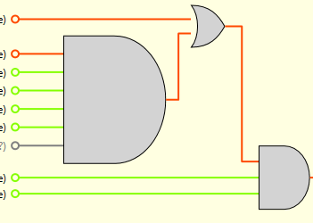
Although now I take a look at it, the Logic Circuit sample doesn’t seem to set the LocationSpot=“Center” on the nodes. I think it’s depending on the size of the nodes and the relative positions of the ports to make the links usually line up straight. This is what you were thinking was a strategy to get the results you wanted. When there is a variable number of inputs, that might get trickier, although you can arrange the ports to be a fixed distance apart.
I think you just wrote the guideline I was searching for:
If you have single connections, you can get rid of the port and use the link going to the middle of the node and to ensure it matches the grid, you go with LocationSpot being in the Center.
If you need multiple connections and are using ports, you need to have these ports aligned on a grid spot relative to the node location spot (which could be center or other). I’m ok to build ports with a fixed distance between them and it is probably the right approach.