I want to place a few ports on the border of Nodes containing shapes such as cloud, ellipse etc.
Is this possible?
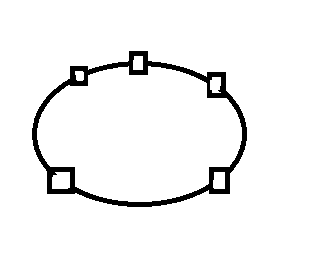
Here is an rough sketch depicting what i want. The rects on the border of the ellipse shape are the ports where links can be drawn.
I want to place a few ports on the border of Nodes containing shapes such as cloud, ellipse etc.
Is this possible?
Here is an rough sketch depicting what i want. The rects on the border of the ellipse shape are the ports where links can be drawn.
Sure, you can do that. It would be easiest if you used a “Spot” Panel whose main element was the Shape or was another Panel holding that Shape, and whose other elements were the port elements that you positioned (by setting GraphObject.alignment) at whatever spots you like.
But are you sure that you want to have independent port elements at various spots along the outer border of those Shapes? How are you going to determine how many ports there should be and where they should be?
Perhaps you don’t need to have a variable bunch of port elements belonging to each Node, but instead you just have Shapes at the end(s) of the Links, belonging to the Links rather than to the Nodes.
Yes, That is my requirement. I have to display some ports on the border of a cloud shape which should depict a network diagram. The links shall be drawn from/to these ports of the shape. I am using a Auto Panel which holds the shape and a text.
I am using the approach given in the dynamic ports sample. (Dynamic Ports), But as you know, the ports are getting placed on the interior border of the whole panel ( and exterior to the shape) instead because these ports are contained in their respective panels ( as mentioned in the sample) and the fromSpot and toSpot are set to top,right,bottom,left.
I want a Node having a container(panel) which holds the shape and text on it. Now the ports should be placed on the border of the shape itself, not on the panel as a whole.
Is there a way where I can create a panel where the ports will be positioned on the curvy border of the shape? I have to dynamically add these ports on the go, where the alignment will be specified by the user, just like in the sample.
for example, if the user clicks on “add top port” in the context menu, a port should be added to the top of ellipse/cloud shape on its border as shown in the image which I uploaded before, not to the panel. I hope you have understood the issue.
Yes, as I just said above, use a “Spot” Panel where the main/first element is your Shape such as an ellipse, and where the rest of the elements are each ports with an alignment and with the usual port-related properties.
If the number of ports will vary, bind the Panel.itemArray and make sure the Panel.itemTemplate is a Panel that holds (or is) your port element(s). The Dynamic Ports sample uses four separate item arrays, one for each side, but you only need one, where all of the elements can be placed anywhere relative to the main Shape of the “Spot” Panel.
This is exactly how the Pipes sample defines its node template, so that each node can have a different number of ports positioned at different points along the edges of its main shape. Pipes