Here is one possible solution, assuming you don’t need to nest:
<!DOCTYPE html>
<html>
<head>
<title>Minimal GoJS Sample</title>
<!-- Copyright 1998-2020 by Northwoods Software Corporation. -->
<meta charset="UTF-8">
<script src="go.js"></script>
<script id="code">
  function init() {
    var $ = go.GraphObject.make;

    myDiagram =
      $(go.Diagram, "myDiagramDiv",
        {
          isReadOnly: true,
          layout: $(go.TreeLayout, { layerSpacing: 20 })
        });

    myDiagram.nodeTemplate =
      $(go.Node, "Spot",
        { selectionObjectName: "BODY" },
        $(go.Panel, "Auto",
          { name: "BODY", width: 80, height: 35 },
          $(go.Shape,
            { fill: "white" },
            new go.Binding("fill", "color")),
          $(go.TextBlock,
            new go.Binding("text"))
        ),
        // in place of links connecting with each node
        $(go.Shape, "LineH", { alignment: go.Spot.Left, alignmentFocus: go.Spot.Right, width: 10, height: 0 }),
        $(go.Shape, "LineH", { alignment: go.Spot.Right, alignmentFocus: go.Spot.Left, width: 10, height: 0 })
      );

    myDiagram.nodeTemplateMap.add("Split",
      $(go.Node,
        { locationSpot: go.Spot.Center },
        $(go.Shape, "Circle",
          { fill: "white", desiredSize: new go.Size(6, 6) })
      ));

    myDiagram.nodeTemplateMap.add("Merge",
      $(go.Node,
        { locationSpot: go.Spot.Center },
        $(go.Shape, "Circle",
          { desiredSize: new go.Size(6, 6) })
      ));

    myDiagram.linkTemplate =
      $(go.Link,
        { selectable: false, routing: go.Link.Orthogonal },
        $(go.Shape)
      );

    // define the Group template to be fairly simple
    myDiagram.groupTemplate =
      $(go.Group, "Auto",
        { layout: $(go.GridLayout, { wrappingColumn: 1, cellSize: new go.Size(1, 1) }) },
        $(go.Shape, { fill: "transparent" }),  // draws vertical segments as if links connecting each node
        $(go.Placeholder, { padding: new go.Margin(-17.5, 0) })  // half the node height
      );

    myDiagram.model = new go.GraphLinksModel(
    [
      { key: 0, category: "Split" },
      { key: 9999, category: "Merge" },
      { key: -1, isGroup: true },
      { key: 10, text: "Alpha 1", color: "lightblue", group: -1 },
      { key: 11, text: "Alpha 2", color: "lightblue", group: -1 },
      { key: 12, text: "Alpha 3", color: "lightblue", group: -1 },
      { key: -2, isGroup: true },
      { key: 20, text: "Beta 1", color: "orange", group: -2 },
      { key: 21, text: "Beta 2", color: "orange", group: -2 },
      { key: -3, isGroup: true },
      { key: 30, text: "Gamma", color: "lightgreen", group: -3 },
      { key: -4, isGroup: true },
      { key: 40, text: "Delta 1", color: "pink", group: -4 },
      { key: 41, text: "Delta 2", color: "pink", group: -4 }
    ],
    [
      { from: 0, to: -1, },
      { from: -1, to: -2 },
      { from: -2, to: -3 },
      { from: -3, to: -4 },
      { from: -4, to: 9999 }
    ]);
  }
</script>
</head>
<body onload="init()">
  <div id="myDiagramDiv" style="border: solid 1px black; width:100%; height:600px"></div>
</body>
</html>
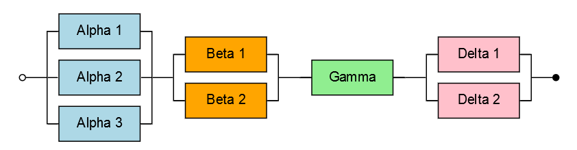
The result:
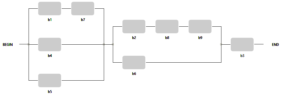
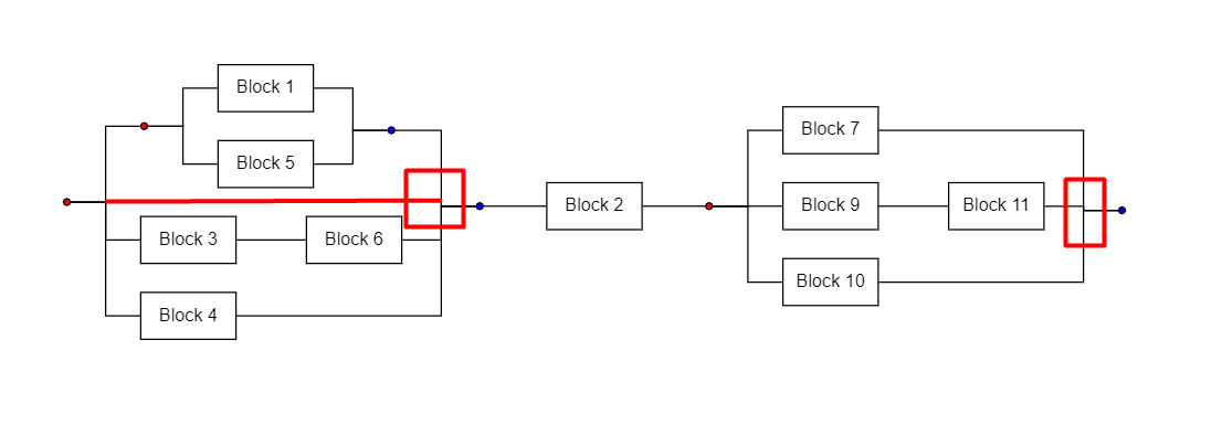
The idea for the model is that you just need to define a bunch of groups, basically one per “column”, and you define the relationships between the groups so that you get the ordering that you want.
I suppose the “Split” and “Merge” (a.k.a. “Begin” and “End”) nodes don’t need to be part of the model – they could be added whenever one loads a model.