Resize Spot node with "external" shapes

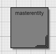
I wish to create a resizable node, with a main shape (rectangle) and some external shape ‘decoration’. Here is an example where I have used a Spot node following by a textblock and custom geometry to create the look of a multi-document icon as follows:

image

Here is my code:

var nodeTemplate =
$(go.Node, "Spot",  
{
	selectionAdorned: true
  , resizable: true
  //, desiredSize: new go.Size(100, 100)
}
, $(go.Shape    , "Rectangle",  // spot positions in the the mopde are aligned with     respect to this
				{
				  fill: "lightgray"
				, strokeWidth: 2
				, portId: ""
				, cursor: "crosshair"
				, fromLinkable: true, fromLinkableSelfNode: true,     fromLinkableDuplicates: true
				, toLinkable: true, toLinkableSelfNode: true, toLinkableDuplicates: true
				, fromSpot: go.Spot.AllSides
				, toSpot: go.Spot.AllSides
				}
  )
, $(go.TextBlock,
				{
			  name: "TitleTextBlock"
			, alignment: new go.Spot(0.5,0, 0, 5) 
			, alignmentFocus: go.Spot.Top
			, font: "bold 16px sans-serif"
			, editable: true
			, text: "some node title"
			, background: "lightcyan"
			, wrap: go.TextBlock.WrapFit
			}
  )
, $(go.Shape    ,
				{ // this geometry creates the multiple document shadow
				  geometry: go.Geometry.parse("M-95,0 h95v-95 M-90,5 h95 v-    95")
				, strokeWidth: 2
				, alignment: new go.Spot(1, 1, 10, 10) 
				, alignmentFocus: go.Spot.BottomRight             
				}
  

  )                  
);  // end Node

I have two problems; which I can’t seem to solve:

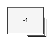
  1. As soon as I resize the node the custom geometry seems to disappear behind the rectangle. I thought the whole point of the Spot is that you make it relative to the rectangle position?

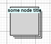
  2. The text in the node title is not wrapping. I would like it to be contained inside the node, which means either make it wrap or force the node to resize when you edit the title; or even when the node is initially drawn with the default text. How could you achieve either of these things?

You might find it easier to define a figure, like the “MultiProcess” figure in the Figures.js extension shown at GoJS Shapes, where the figure includes all of the geometry, so that when the Shape is resized, new Geometry is generated that has the effects that you want when considering the desired width and height.

The problem with the Figures.js and the multiprocess figure is that it uses vector geometry which means it sizes the “shadow” process when the shape is sized. This is not what I want I just want those extra shadow lines to appear on the outside of the shape at the same distance, when the shape is made bigger or smaller.

I made it work by putting the lines on the inside of the shape like this.

image

However if it can be made to work by putting on the outside, would be interested to know how.

NB: I get the same problem when I add any shape. that is outside the bounds of the main rectangle. looks fine when its first displayed and as soon as I size the rectangle the shape disappears.

<!DOCTYPE html>
<html>
<head>
  <title>Minimal GoJS Sample</title>
  <!-- Copyright 1998-2022 by Northwoods Software Corporation. -->
</head>
<body>
  <div id="myDiagramDiv" style="border: solid 1px black; width:100%; height:800px"></div>
  <script src="https://unpkg.com/gojs"></script>
  <script id="code">
function init() {
  const $ = go.GraphObject.make;

  myDiagram = new go.Diagram("myDiagramDiv");

  myDiagram.nodeTemplate =
    $(go.Node, "Spot",
      { resizable: true, resizeObjectName: "SHAPE", selectionObjectName: "SHAPE" },
      $(go.Panel, "Auto",
        $(go.Shape, "Rectangle",
          { name: "SHAPE", fill: "whitesmoke", width: 140, height: 100 },
          new go.Binding("desiredSize", "size", go.Size.parse).makeTwoWay(go.Size.stringify)),
        $(go.TextBlock,
          new go.Binding("text", "key"))
      ),
      $(go.Shape, {
        geometryString: "M40 0 L40 40 0 40 M43 3 L43 43 3 43",
        alignment: go.Spot.BottomRight,
        alignmentFocus: new go.Spot(1, 1, -6, -6),
      }),
    );

  function updateLinkSpots(link, oldport, newport) {
    if (link.fromNode !== null && link.fromNode === link.toNode) {
      link.fromSpot = new go.Spot(1, 0.999, 0, -20);
      link.toSpot = new go.Spot(0.999, 1, -20, 0);
    } else {
      link.fromSpot = go.Spot.Default;
      link.toSpot = go.Spot.Default;
    }
  }

  myDiagram.model = new go.GraphLinksModel(
    {
      nodeDataArray: [
        { size: "80 60" }
      ]
    });
}
window.addEventListener('DOMContentLoaded', init);
  </script>
</body>
</html>

image

Thanks Walter, this was instructive for me and I may use it elsewhere, however I realised your earlier suggestion of using geometry (with height, and width) which I I initially dismissed is a cleaner and better solution. I thought it was just like SVG or geometry strings, however I now see that using the height and width is much more flexible and scales properly.

This was my solution:

go.Shape.defineFigureGenerator("MultiDoc", function(shape, w, h) {  

return new go.Geometry()

         .add(new go.PathFigure(0, 0)
         .add(new go.PathSegment(go.PathSegment.Line, w-8, 0))
         .add(new go.PathSegment(go.PathSegment.Line, w-8, h-8))
         .add(new go.PathSegment(go.PathSegment.Line, 0,   h-8).close()) // this creates the square

         .add(new go.PathSegment(go.PathSegment.Move, w-8, 4))
         .add(new go.PathSegment(go.PathSegment.Line, w-4, 4))     
         .add(new go.PathSegment(go.PathSegment.Line, w-4, h-4))
         .add(new go.PathSegment(go.PathSegment.Line,   4, h-4))
         .add(new go.PathSegment(go.PathSegment.Line,   4, h-8))
         .add(new go.PathSegment(go.PathSegment.Move, w-4  , 8))
         .add(new go.PathSegment(go.PathSegment.Line, w    , 8))
         .add(new go.PathSegment(go.PathSegment.Line, w  , h))
         .add(new go.PathSegment(go.PathSegment.Line, 8 , h))
         .add(new go.PathSegment(go.PathSegment.Line, 8 , h-4))
         );          
});

I have marked your first suggestion as correct, and added this for others benefit.

Yes, the point of Figures is to support parameterized geometry generation. It is more complex to implement though than a simple scaling SVG geometry. Usually I run into problems dealing with small sizes. In your case, what should you generate when the given width or height is 8 or less?

I take your point, the smallest size I use is a width of about 30 by 30, so that’s not a problem for me.