Hi Walter,
I need to show the inner usable area in my floorplan i.e to show the inner dimensions of the floorplan by neglecting the wall thickness.
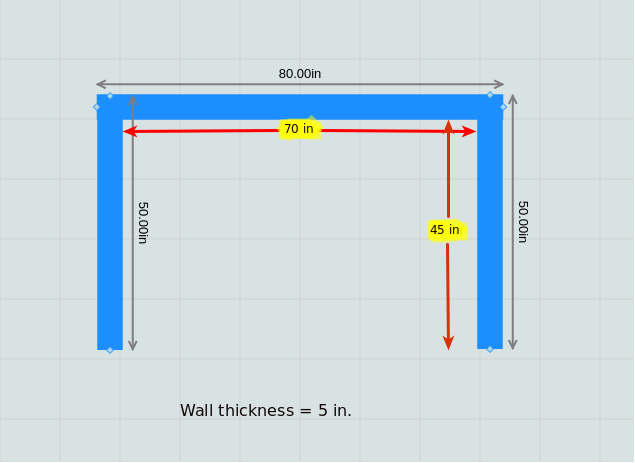
Can you please help me with that ?.
Hi Walter,
I need to show the inner usable area in my floorplan i.e to show the inner dimensions of the floorplan by neglecting the wall thickness.
Can you please help me with that ?.
You’ll have to add a DimensioningLink that goes between a spot on the right side of the left wall and a spot on the left side of the right wall.
Hi Walter,
Sorry for late response, am trying to implement DimensioningLink with my FloorPlanner but am getting this error message in my console “Uncaught Error: A GraphObject can only be added to a Panel, not to: Shape(None)#1466k”.
Can you please help me to figure out the issue.
Below is my code:
function makeWallGroup() {
var $ = go.GraphObject.make;
return $(go.Group, “Spot”,
{
contextMenu: makeContextMenu(),
toolTip: makeGroupToolTip(),
selectionObjectName: “SHAPE”,
rotateObjectName: “SHAPE”,
locationSpot: go.Spot.Center,
reshapable: true,
minSize: new go.Size(1, 1),
dragComputation: snapWalls,
selectionAdorned: false,
mouseDrop: addWallPart,
mouseDragEnter: wallPartDragOver,
mouseDragLeave: wallPartDragAway,
doubleClick: function (e) { if (e.diagram.floorplanUI) e.diagram.floorplanUI.hideShow(“selectionInfoWindow”); }
},
$(go.Shape,
{
strokeWidth: 1,
name: “SHAPE”,
fill: “black”,
stroke: “red”,
geometry: new go.Geometry(go.Geometry.Line),
isGeometryPositioned: true
},
$(DimensioningLink,
new go.Binding(“fromSpot”, “fromSpot”, go.Spot.parse),
new go.Binding(“toSpot”, “toSpot”, go.Spot.parse),
new go.Binding(“direction”),
new go.Binding(“extension”),
new go.Binding(“inset”),
$(go.Shape, { stroke: “gray” },
new go.Binding(“stroke”, “color”)),
$(go.Shape, { fromArrow: “BackwardOpenTriangle”, segmentIndex: 2, stroke: “gray” },
new go.Binding(“stroke”, “color”)),
$(go.Shape, { toArrow: “OpenTriangle”, segmentIndex: -3, stroke: “gray” },
new go.Binding(“stroke”, “color”)),
$(go.TextBlock,
{
segmentIndex: 2,
segmentFraction: 0.5,
segmentOrientation: go.Link.OrientUpright,
alignmentFocus: go.Spot.Bottom,
stroke: “gray”,
font: “8pt sans-serif”
},
new go.Binding(“text”, “”, showDistance).ofObject(),
new go.Binding(“stroke”, “color”))
),
new go.Binding(“strokeWidth”, “thickness”),
new go.Binding(“stroke”, “isSelected”, function (s, obj) {
if (obj.part.containingGroup != null) {
var group = obj.part.containingGroup;
if (s) { group.data.isSelected = true; }
}
return s ? “dodgerblue” : “black”;
}).ofObject()
))
}
That is an error because one cannot add a Part (in this case a DimensioningLink) to a Panel.
It means that it is not possible to show the inner dimensions of walls as of in the above diagram with the help of DimensioningLink …?
Just add the Link to the diagram, not to a Panel.
The DimensioningLink can be modeled or not. (I.e. have Link.data in the model.)
But how can i add DimensioningLink to the walls which is getting generated dynamically by user on mouse drag…?
I think you’ll need to extend the behavior of the Floorplan.updateWallDimensions and/or Floorplan.buildDimensionLinks methods to include your additional links.
Walter is right, you will need to extend the behavior in Floorplan.updateWallDimensions(). A couple notes
// if there's 1 Dimension Link for this wall (link has soloWallFlag), adjust to/from pointNodes of link, rather than deleting / redrawing
                if (soloWallLink !== null) {
                    // since this is the only Dimension Link for this wall, keys of its pointNodes will be (wall.data.key) + 1 / (wall.data.key) + 2
                    var linkPoint1 = null; var linkPoint2 = null;
                    floorplan.pointNodes.iterator.each(function (node) {
                        if (node.data.key === part.data.key + "PointNode1") linkPoint1 = node;
                        if (node.data.key === part.data.key + "PointNode2") linkPoint2 = node;
                    });
                    var startpoint = part.data.startpoint; var endpoint = part.data.endpoint;
                    // adjust  left/top-most / right/bottom-most wall endpoints so link angle is correct (else text appears on wrong side of Link)
                    var firstWallPt = ((startpoint.x + startpoint.y) <= (endpoint.x + endpoint.y)) ? startpoint : endpoint;
                    var lastWallPt = ((startpoint.x + startpoint.y) > (endpoint.x + endpoint.y)) ? startpoint : endpoint;
                    var newLoc1 = floorplan.getAdjustedPoint(firstWallPt.copy(), part, part.rotateObject.angle, 10);
                    var newLoc2 = floorplan.getAdjustedPoint(lastWallPt.copy(), part, part.rotateObject.angle, 10);
                    linkPoint1.data.loc = go.Point.stringify(newLoc1);
                    linkPoint2.data.loc = go.Point.stringify(newLoc2);
                    soloWallLink.data.angle = part.rotateObject.angle;
                    linkPoint1.updateTargetBindings();
                    linkPoint2.updateTargetBindings();
                    soloWallLink.updateTargetBindings();
                    //** INSERT CODE HERE **/
                }
                    // else build a Dimension Link for this wall; this is removed / replaced if Dimension Links for wallParts this wall are built
                else {
                    var startpoint = part.data.startpoint;
                    var endpoint = part.data.endpoint;
                    var firstWallPt = ((startpoint.x + startpoint.y) <= (endpoint.x + endpoint.y)) ? startpoint : endpoint;
                    var lastWallPt = ((startpoint.x + startpoint.y) > (endpoint.x + endpoint.y)) ? startpoint : endpoint;
                    floorplan.buildDimensionLink(part, 1, firstWallPt.copy(), lastWallPt.copy(), part.rotateObject.angle, 10, true, floorplan);
                   //** INSERT CODE HERE **/
                }
These problems only compound when examining other cases. Observe
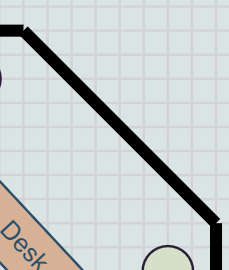
Calculating the internal Dimension Link for the diagonal wall here would be even more difficult, as clearly you could not just take its endpoints and subtract some percentage of its neighboring wall’s thickness, as that ignores the angle at which it connects to its neighboring walls.
None of this is to say what you want to do is impossible, but be aware it will require a lot of work and careful consideration of different cases.
Hi Ryanj,
Is it possible to make perfect corner? If yes how it can be achieve?
I am dealing with only the first case scenario (i.e onlt straight walls).
Thanks.
There is no easy way to get that effect. The closest that I can think of, while keeping each wall segment a separately selectable and movable Part, would be to modify the Geometry of the end of one segment so that it properly buts up against all of nearby neighboring segment ends.
But this would be significant work.