Hi there,
we are using GoDiagram 4.0.0.2, although i could reproduce the same issue with the latest version.
We have some bidirectional ports, so we put them both on the left side. When we connect them, the stroke shows some strange paths.
I created a small sample, here a breief description of it:
I have 2 nodes at 40,40 and 80,80, both having a left port which are connected. I use a right directed LayeredDigraph. If I set the source port FromSpot = GoObject.MiddleLeft andlayout the graph, the path writes a strange Z like shape. We see it in much more complex scenarios always with the path having points as if it would like to arrive on the other side of the node.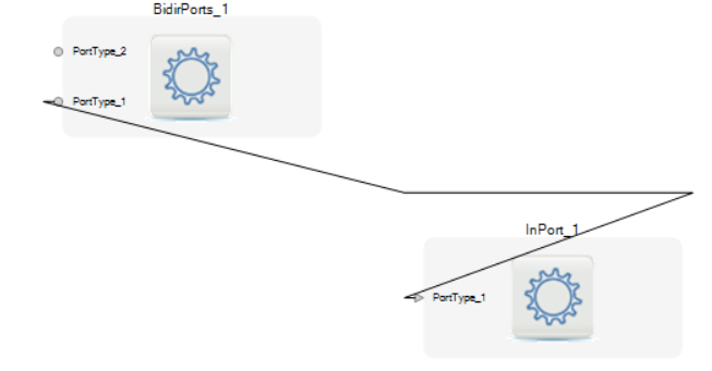
Any ideas?
Find below the source for the repro (just create a console app with this file as program.cs, and add reference to Go and Go.Layout
    using System;
    using System.Drawing;
    using System.Linq;
    using Northwoods.Go;
    using Northwoods.Go.Layout;

    namespace GoLinkProblem
    {
        class Program
        {
            static void Main(string[] args)
            {
                var datafactory = new DataFactory();
                var document = datafactory.CreateTestDocument();
                var layout = datafactory.GetLayout(document);
                layout.PerformLayout();
                var link = layout.Network.Links.First();

                for (int i = 0; i < link.Stroke.PointsCount; i++)
                {
                    var pointF = link.Stroke.GetPoint(i);
                    Console.WriteLine("{0}: x={1} y={2}", i, pointF.X, pointF.Y);
                }
                Console.ReadLine();
            }
        }

        internal class DataFactory
        {
            public GoDocument CreateTestDocument()
            {
                var view = new GoView();
                var result = view.Document;

                var vertex1 = new GoGeneralNode
                {
                    Location = new PointF(40, 40),
                    Size = new SizeF(20,20),
                };

                var vertex2 = new GoGeneralNode
                {
                    Location = new PointF(80, 80),
                    Size = new SizeF(20, 20)
                };

                var fromPort = new GoGeneralNodePort
                {
                    FromSpot = GoObject.MiddleLeft // this makes all the difference
                };
                vertex1.AddLeftPort(fromPort);
                var toPort = new GoGeneralNodePort();
                vertex2.AddLeftPort(toPort);
                var link = new GoLink
                {
                    FromPort = fromPort,
                    ToPort = toPort,
                };
                link.AdjustingStyle = GoLinkAdjustingStyle.End; // this makes all the difference
                link.SetPoints(new PointF[] {new PointF(40, 50), new PointF(35, 50), new PointF(75, 90), new PointF(80, 90),    });

                result.Add(vertex1);
                result.Add(vertex2);
                result.Add(link);

                return result;
            }

            public GoLayoutLayeredDigraph GetLayout(GoDocument document)
            {
                var result = new GoLayoutLayeredDigraph();
                result.DirectionOption = GoLayoutDirection.Right;
                result.SetsPortSpots = false;
                result.Document = document;
                return result;
            }
        }
    }