Hello friends. I have successfully built a diagram with the correct edges and shapes, but all the nodes render together in a manner, like so:
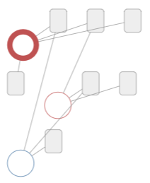
###Current
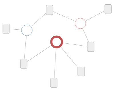
However I desire this type of layout.
###Desired
Key features are:
Red root node is always in the center. Eventually I will make other nodes in the center, but calling this one out for sake of example.
Other nodes space around the “root” node with as few overlapping edges as possible.
###Attempted Solutions
I’ve unsuccessfully tried using variations of ForceDirectedLayout to replicate this layout.
My problems with ForceDirectedLayout were:
Unable to move root node into the center. While I could move it manually by hooking on to initialLayoutCompleted as @walter suggested, the final layout would always look messy.
Unpredictable layouts – sometimes a lot of edges would overlap, sometimes it would look beautiful. Turning off the internal randomizer did not help.
TLDR;
Basically, I have the feeling that I am approaching this problem incorrectly, and am probably using the wrong type of layout? Perhaps there is a better built in layout to render a design like this? I feel like this is a common design, and am struggling to achieve it!
Does anyone have any suggestions or have you achieved a similar layout? Any direction or suggestions are greatly appreciated.
It seems you want to use something like CircularLayout but you need to use something like ForceDirectedLayout because you want to spread out the nodes that do not form a ring around the “root node”.
I haven’t tried this, but one possibility is to perform a CircularLayout, then move the “root node” into the center, and then perform a ForceDirectedLayout.
Something like:
  function layout(diagram) {
    diagram.startTransaction();
    var clay = new go.CircularLayout();
    clay.doLayout(diagram);
    var root = ... find root Node of diagram ...;
    if (root !== null) root.location = clay.actualCenter;
    var flay = new go.ForceDirectedLayout();
    flay.doLayout(diagram);
    diagram.commitTransaction("layout");
  }
Pardon any typos. You might need to fiddle with the layout properties too.
@walter thanks again for the suggestions. I would have never thought to do post-processing on the initial layout with other layouts. I tried two ways by doing “post-processing” using the initialLayoutCompleted hook for myDiagram. I used setTimeout so I could visually see what exactly was happening.
###Experiment#1
The first was what you suggested:
Apply a CircularLayout
Move root node into the center of the circular layout
Apply a ForceDirectedLayout with a overridden makeNetwork to set the root node vertex.isFixed = true
Here is a GIF of 3 refreshes of this render method:
Notice the nodes seem generally well spread out.
###Experiment#2
I then thought to try another method by moving the entire graph to the middle instead of relying on CircularLayout to find the middle. The process for this was like so:
Render myDiagram with default layout
Move root node to center of myDiagram using myDiagram.centerRect
Apply a ForceDirectedLayout with a overridden makeNetwork to set the root node vertex.isFixed = true
Here is a GIF of this experiment:
Notice on this the nodes seem to stay clustered more often.
Conclusion
I will be going with the Experiment #1 process. I had thought they two experiments were effectively doing the same thing:
Render
Somehow move root node to center
Apply ForceDirectedLayout
But for some reason, if you first apply a CircularLayout the results seem to be better. I don’t quite understand why though, perhaps it is chance? :)
I do suggest trying it with many more graphs, to make sure the results are acceptable. In particular I’m concerned that when there are many nodes the results might not be so good.
After further experimentation, unfortunately it seems doing a Circular layout before a ForceDirected actually doesn’t really do anything. As you suspected @walter, when you add more nodes or some size, it breaks:
Notice how much the root node jumps. Will keep continuing to try to figure this out out.
I still think your basic requirement is unreasonable. Let’s say the “root” node is named “A”. If the whole graph is just “A” --> “B”, how could “A” possibly be in the middle of the diagram? (Unless you want “A” and “B” to be coincident – i.e. overlapping, which I think is unreasonable.) I can come up with other graphs where plausible layouts produce results where the “root” should not be at the center.
Are you sure that your code is actually positioning the “root” vertex to be at the center of the result of the CircularLayout? It didn’t appear that way in your first animated GIF.
@walter You raise a very good point in that the basic requirement is unreasonable. As I add more and more nodes to my experiments, it does feel like I should just let ForceDirected do its thing. I will play around with it a little more then mark a solution.
That depends entirely on your app – I cannot know what node you want to center. Maybe you want to call Diagram | GoJS API or another Diagram method that finds you the node you want.