I want to implement a diagram where a single port shall be accessible to two or more elements.
This is useful for rendering a diagram where a network element like a router can reside on the border of two elements/groups.I hope you understand what I mean. In this case I am considering a router to be as a port because i want the routers to reside on the border.
Can you tell me how can I implement this.
Any alternative suggestions is also appreciated.
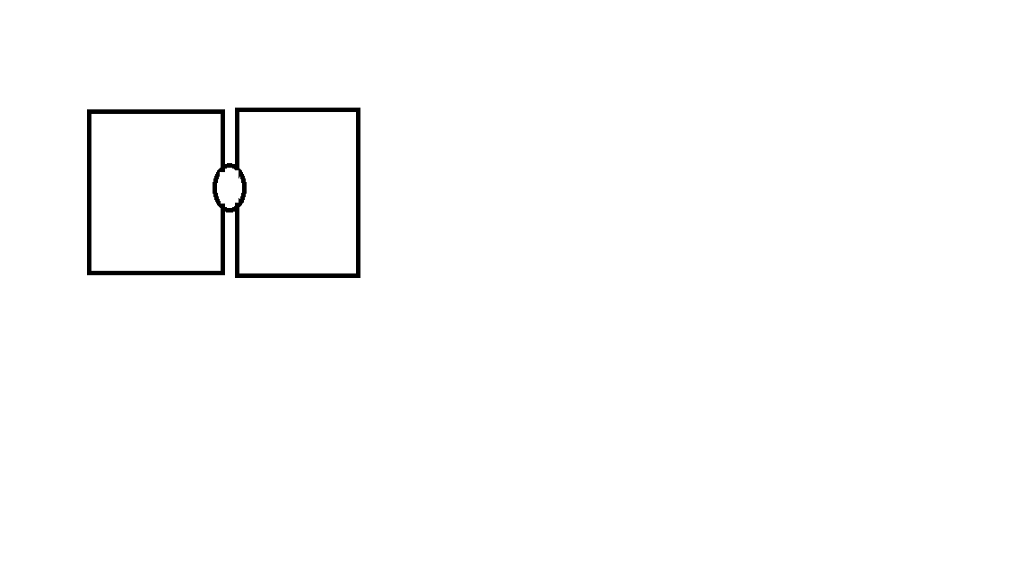
No, I’m sorry, but I don’t understand. Could you show two sketches or screenshots showing the two elements and one port, before and after one of the elements is deleted?
OK, that makes your requirement clearer. So you do not want behavior like the Pipes sample, which is where I thought you were going. This is because the Pipes sample does use links, even though the user cannot see them.
If you do not want any links you do not need to use “ports” as GoJS defines them. However links do provide an easy way for a node to refer to another node.
So it seems to me the port belongs to just one of the nodes. In what manner did you want node B to have access to node A’s port? Does node A care about node B at any time?
The port simply represents a point of contact between A and B. I cannot use links because the sketch shows two elements connected via a component on their borders. So I thought port is a good idea to represent this component.
If these nodes are connected , and the user moves one of the nodes, then the other node should move along with it.( including the component).
3.Pipes sample is almost close to my requirement. But there will be other ports on the node(in this case, node A) which will be connected to other nodes using links( yes, links). But A will be directly connected to B using a port.
Were you referring to the Pipes sample? You could have two different categories of links – both the regular kind and the kind that are used in Pipes, not-visible bodiless Links.
I cannot draw links from one pipe to the other in the pipes sample. I cannot find any additional ports on the pipes to draw the links. Am I missing something? Apologies if I am bothering you. I am a beginner.
You would need to redesign the nodes to allow that, and the code that deals with nodes that are attached to each other to ignore the regular category of links.
Actually, there are two ports superimposed on each other – that’s how the code knows how to position the nodes relative to each other.
Furthermore, when there is a link between two ports (and there can be at most one in that sample), the ports become invisible. See the Node.linkConnected and Node.linkDisconnected event handlers.
That’s one way to do it. But I still don’t understand all of your requirements – I was just guessing that the Pipes sample basically did what you wanted.
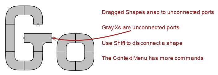
Take a look at the new Pipes sample for version 1.7, at Pipes. If you diff the sources, you will see what changes were made in order to support additional kinds (categories/templates) of links.
In that sample add this link data object at the end of the array: , {"from":2, "to":21, "tid":"U0", "category":"Comment"}
And then “Load” the model. You’ll get this result:
I am trying to implement the snapping tool which is present in the pipes sample but I am facing some issues. My diagram is having some groups in which the nodes are embedded. I have modified the SnappingTool.prototype.moveParts function to ignore the rest of the code if node is instance of group, but when I drag the group in the diagram, the children in the group are not moving along with it. How do I perform the check in SnappingTool.prototype.moveParts to ignore the groups for snapping?
If you are modifying the behavior of DraggingTool.moveParts, that is the basic function that implements the moving of a collection of Parts by the DraggingTool, so you can do whatever you want. You’ll need to debug your code methodically.
I have modified the behaviour of the Dragging tool. It is working fine . Thanks to you!
I have another issue, In the pipes sample , the location of the nodes in the diagram are hardcoded in the json initially. That is how they appear connected. If we modify the “loc” attributes in the text area, they do not seem connected.
I cannot supply the initial location in json for my diagram. For this, I am using the Diagram layouts.
The problem here is when I supply the link data initially, the elements get connected to each other but not at their specific ports, instead they are positioned somewhere else which is determined by the layout.The link is working fine as when I move one element the connected element moves along with it.
Is there anyway I can specify that the nodes should be connected at their ports?
The Pipes sample app is designed for users to manually position parts near each other. The DraggingTool will snap them together properly. The snapping functionality is in that custom SnappingTool.moveParts method, but the code is not organized to be used by a custom Layout, which is what you seem to need to implement yourself.