Adding Color bar and some Geometry With the nodes

I have Crop marks implemented as

Now I want to implement something as shown in the screen shot.
I want to put a color mark. That can be an image and I want it to be dynamic such that I can put that on left right top or bottom of the canvas.
Current screenshot shows the color bar on right hand side of the canvas.
Other than that I want to ask that is there any possibility to draw bull eyes as shown at the corners of each extreme end marked as red circles.
I can share code if required.

If you want to use an existing image for the color bar, use a Picture in a Part. Set its Part.position to be where you want it to be, and set/bind the Picture.angle appropriately.

If you want to draw the color bar yourself rather than using an image, the Part can be either a “Vertical” or a “Horizontal” Panel containg a bunch of Shapes with the desired Shape.fill and a zero Shape.strokeWidth.

For the bulls-eye parts, you can create what you need using one or more Shapes. These descriptions should help: GoJS Shapes -- Northwoods Software and GoJS Geometry Path Strings -- Northwoods Software

@walter
Thanks Your Idea worked for me to some extent.

$scope.addColorBar = function () {
scope.myDiagram.add( (go.Part, “Horizontal”,
{ alignment: go.Spot.Right,position : new go.Point(100, 100),angle: 90},
(go.Panel, "Horizontal", (go.Picture, { source: “colorBar.jpg” ,desiredSize: new go.Size($scope.totalDiagramHeight, NaN),position : new go.Point(100, 100), alignment: go.Spot.Right , imageStretch: go.GraphObject.Fill}
)
)
))
};

This is what I am using.
But I want the color bar to be on right left top or bottom edges of the canvas.
Do you have any idea using which I can stick the color bar on the sides.

Current behavior screenshot:

You have to set the Part.position to be where you want it.

I suggest setting the angle on the Picture, not on the Part.

You don’t need an intermediate Panel because it only has a single element in it.

@walter
$scope.addColorBar = function () {
$scope.myDiagram.add(
$(go.Part, “Horizontal”,
{alignment: go.Spot.Right, position: new go.Point(0 , 0)},
$(go.Picture, {
source: “colorBar.jpg”,
angle: 90,
desiredSize: new go.Size($scope.totalDiagramHeight, NaN),
alignment: go.Spot.Right,
imageStretch: go.GraphObject.Fill,
position: new go.Point(1000,1000 )
})
))
};

I am trying to set position on both part and picture but none of them is getting reflected.
Looks like color bar is getting the same location as of the nodes.

  $(go.Part,
    { position: new go.Point(..., ...), layerName: "Grid" },
    $(go.Picture, "colorBar.jpg",
      { angle: 90 })
  )

You need to fill in the x and y of the position, presumably based on the area of the Nodes that you have already created and positioned.

I took the liberty of putting this part in the “Grid” layer so that it is behind all of the usual nodes (and links, if you have any). Also, if you show them in the interactive Diagram, the user will not be able to select them.

Thanks @walter fir your quick responses.
It worked for me.
I will play with it to put it at extreme ends.

If you implemented your node template as a Node, then myDiagram.nodes returns a collection of the nodes but not of any of the simple Parts such as your bulls-eyes or colorbar.

In that case myDiagram.computePartsBounds(myDiagram.nodes) will return the area occupied by all of your nodes. However, if you have multiple “pages”, you’ll need to call computePartsBounds on just the subset of Nodes on each “page”.

I totally got your point here @walter.
I have a little concern about positioning of part.
Do we have anything like location spot: left right top bottom that I can implement on Part instead of position.
Because for position I have to give specific x,y points and when i will change the aspect ratio of the canvas I have to change them.
Is there any other way such that I can place the color bar at top bottom right left positions of the canvas.
I am sorry if I am asking too much.
I hope you got my point.

No, sorry, but there is no such functionality. You could write your own custom Layout that you could install as the Diagram.layout to do what you want, though.

The closest would be the TableLayout, which you can find in the extensions directory. The sample using that layout is at Table Layout.

@walter
Sorry walter but I believe this logic is not working for me. Part considers its origin point to be at the point from where a node starts. Second thing if I add delete or resize any node inside the canvas then this color bar moves accordingly.
It is too much to calculate and place that color bar at extreme ends.
It is impossible for me to calculate the positioning in a dynamic canvas.

So you are using TableLayout already? If so, what is the specific problem that is insoluble?

@walter I am using GridLayout
I cannot switch to TableLayout as I have spent two months on grid layout already.
My actual problem is suppose I have drawn the color bar and manage to set that vertically on the right side of the canvas.
But when I will draw the other nodes inside the canvas then the canvas will spread out and the vertical color bar will go out of the view(outside the canvas width) .
My expectation is the my color bar should be floating on either extreme end of the canvas.
My application works like it will first draw the nodes then the color bar is set on either of the four sides. But when I resize the nodes then again the color bar location gets messed up.

Yes, GridLayout was suitable until now. But you have added requirements, so you need to change your implementation.

@walter I have another question

I am trying to add a new shape to my nodes using

$scope.addStarTarget = function () {
				$scope.myDiagram.add(
					
					$(go.Part,
					$(go.Shape,"Circle", {alignment: new go.Spot(1,0,5,-5),desiredSize: new go.Size(10, 10)}) // Top Left
				)
				)
			}; 

It is not adding the circular star target

But if I try to add this inside Node then it works fine

$scope.myDiagram.nodeTemplate =
				$(go.Node, "Spot",
					{
						//stretch: go.GraphObject.Horizontal,
						locationSpot: go.Spot.TopLeft,
						resizable: true,
						name: 'shape',
						locationObjectName: 'shape',
						resizeObjectName: 'shape', // user can resize the Shape
						selectionAdorned: false, // no selection handle when selected
					},

					new go.Binding("text", "text"), // for sorting

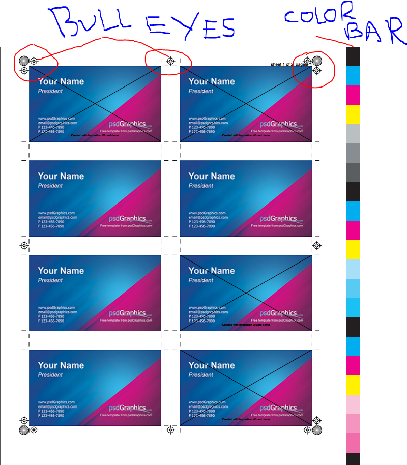
					//Crop marks at each particular location
					$(go.Shape, {alignment: go.Spot.TopLeft, geometry: CutMarkGeometry}),
					$(go.Shape, {alignment: go.Spot.TopRight, geometry: CutMarkGeometry}),
					$(go.Shape, {alignment: go.Spot.BottomRight, geometry: CutMarkGeometry}),
					$(go.Shape, {alignment: go.Spot.BottomLeft, geometry: CutMarkGeometry}),
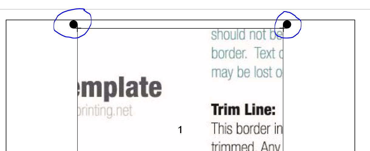
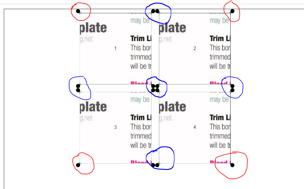
					 $(go.Shape,"Circle", {alignment: new go.Spot(1,1,5,5),desiredSize: new go.Size(10, 10)}),    // Bottom Right
					$(go.Shape,"Circle", {alignment: new go.Spot(1,0,5,-5),desiredSize: new go.Size(10, 10)}),  //Top Right
					 $(go.Shape,"Circle", {alignment: new go.Spot(0,1,-5,5),desiredSize: new go.Size(10, 10)}),  // Bottom Left
					 $(go.Shape,"Circle", {alignment: new go.Spot(0,0,-5,-5),desiredSize: new go.Size(10, 10)}), // Top Left

Inside Node :

Inside Node is working fine
But when I try using part it is not working

Also If there will be two nodes in one row then I need that Circular starTarget only at extreme ends
Referring to the below image I need circular shapes marked with red circles and I want to remove the shapes marked by blue circles.
The below screenshot is working example of shapes inside Node

It depends on the Diagram.layout. Some layouts only works with Nodes and Links. Others work on all Parts. My guess is that you are using a Layout that does not operate on Parts, thereby not giving your Part a position (or location). Without a real position (or location), a Part cannot be drawn.

Make sense now thanks

A post was split to a new topic: Using TableLayout to put color bars on sides