Hi,
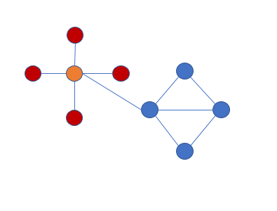
i use now the ForceDirectedLayout. But the end of the nodes must be like a CircularLayout (see the images)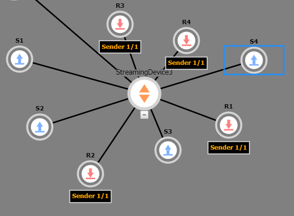
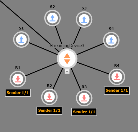
The node S1 - S4 should be above the central node. And the order is important.
How can i implement this. Thx for ideas,
Hi,
i use now the ForceDirectedLayout. But the end of the nodes must be like a CircularLayout (see the images)
The node S1 - S4 should be above the central node. And the order is important.
How can i implement this. Thx for ideas,
I suggest that you put all of the nodes that you show in your screenshot in a Group. The template for the group would set the Group.layout to be an instance of CircularLayout, which would include settings to sort the nodes in the manner that you want.
The template for the group might be completely transparent to the user, if you don’t want to show anything:
    myDiagram.groupTemplate =
      $(go.Group,
        {
          layout: $(go.CircularLayout, { . . . })
        },
        $(go.Placeholder)
      );
In fact, if you make each “last parent” node be a Group, it can work pretty well:
    myDiagram =
      $(go.Diagram, "myDiagramDiv",
          {
            layout: $(go.ForceDirectedLayout)
          });

    myDiagram.nodeTemplate =
      $(go.Node, "Vertical",
        $(go.Shape, "Circle",
          { width: 40, height: 40, fill: "lightgreen" },
          new go.Binding("fill", "color")),
        $(go.TextBlock,
          new go.Binding("text"))
      );

    myDiagram.groupTemplate =
      $(go.Group, "Spot",
        {
          layout: $(go.CircularLayout,
              {
                spacing: 50,
                sorting: . . .,
                comparer: . . .
              })
        },
        $(go.Placeholder),
        $(go.Panel, "Vertical",
          $(go.Shape, "Circle",
            { portId: "", width: 40, height: 40, fill: "lightblue" },
            new go.Binding("fill", "color")),
          $(go.TextBlock,
            new go.Binding("text"))
        )
      );

    myDiagram.model = $(go.GraphLinksModel, {
      nodeDataArray:
      [
        { key: 1, text: "Alpha", color: "lightblue" },
        { key: 2, text: "Beta", color: "orange", group: 5 },
        { key: 3, text: "Gamma", color: "lightgreen", group: 5 },
        { key: 4, text: "Delta", color: "pink", group: 5 },
        { key: 5, text: "Epsilon", isGroup: true },
        { key: 11, text: "Alpha", color: "orange", group: 15 },
        { key: 12, text: "Beta", color: "orange", group: 15 },
        { key: 13, text: "Gamma", color: "lightgreen", group: 15 },
        { key: 14, text: "Delta", color: "pink", group: 15 },
        { key: 15, text: "Epsilon", isGroup: true },
        { key: 21, text: "Alpha", color: "orange", group: 25 },
        { key: 22, text: "Beta", color: "orange", group: 25 },
        { key: 23, text: "Gamma", color: "lightgreen", group: 25 },
        { key: 24, text: "Delta", color: "pink", group: 25 },
        { key: 25, text: "Epsilon", isGroup: true }
      ],
      linkDataArray:
      [
        { from: 1, to: 5 },
        { from: 5, to: 2 },
        { from: 5, to: 3 },
        { from: 5, to: 4 },
        { from: 1, to: 15 },
        { from: 15, to: 11 },
        { from: 15, to: 12 },
        { from: 15, to: 13 },
        { from: 15, to: 14 },
        { from: 1, to: 25 },
        { from: 25, to: 21 },
        { from: 25, to: 22 },
        { from: 25, to: 23 },
        { from: 25, to: 24 },
      ]
    });
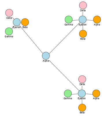
Thx, it works very well. But it is possible to set the nodes on the same y-Position. See the node, gamma, Epsilon, Alpha in your example or in this image:
It’s possible that their centers do have the same Y position – I can’t tell for sure, though.
I suppose if there are one or two (or maybe even three) nodes in the group, you may want to do your own positioning rather than depend on CircularLayout’s positioning behavior. One way to implement that would be to override CircularLayout.commitNodes to see if there are one or two vertexes in the CircularLayout.network and then adjust their positions before calling the super method.
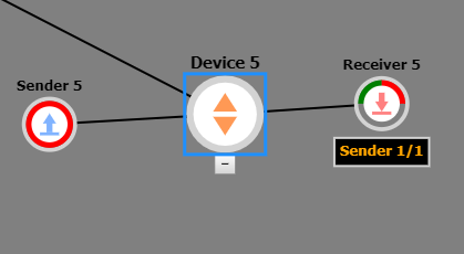
I think I have formulated my question wrongly.
I use diffrent templates for (here: sender / receiver) the nodes. The receiver has a larger height because of the bottom, so the nodes have after the calculation of the layout not the same y-Position. I want that the calculation of the layout includes only the circles. It’s like the property “selectionObjectName” of the node. With the property i want only select the circle. I hope you understand what i mean. ;-)
Yes, I think we agree with why the apparent misalignment is happening – the nodes have different sizes and may be asymmetrical. OK, so you are not concerned with the cases where there is only one or two nodes, but with all numbers of nodes.
Most layout classes try to avoid node overlaps so they take the whole node’s actualBounds into account. Some layouts allow that to be adjusted by setting properties, but in this case I think you’ll need to override CircularLayout.makeNetwork. Call the super method and then iterate over the this.network.vertexes to set each LayoutVertex.width, height, focusX, and focusY to be the values that you want.
It is not possible to separate the template. The template include only the circle and the textboxes are only “added” but not a part of the node. So the selection, calculation, location is only for the circle and textboxes calculate their positions depending on the size and position of the circles.
Or a solution is to add a transparent textbox so the node have the same size. It is possible? To set the “visible” property is the wrong way?
Did you try what I suggested with overriding the layout so that it thinks the nodes it is working with are sized and centered differently than they actually are? I did not suggest modifying your node templates at all.
Another question first: How can i locate the group now, when the central node has a fix position and don’t use the forceddirectedlayout.
Is it sufficient for your purposes to set Group.locationSpot to go.Spot.Center and to call Node.move when wanting to move a Node, including ones that are Groups?
Where or how i call Node.Move?
In your code to move Nodes that happen to be Groups. You say you aren’t using ForceDirectedLayout any more, so either you have implemented your own custom Layout that moves Nodes automatically, or you have your own separate code that assigns node locations by calling Node.move.
Okay it works fine. But i want to move the central node to the new position and not the “group” like an locationObject.
If those parent nodes are not Groups, you can move them as you would any node.
If they are Groups, you could shift the Panel holding a circular Shape and a TextBlock relative to the child/member nodes by changing that Panel’s GraphObject.alignment and the Group.locationSpot to a new go.Spot(0.5, 0.5, offsetx, offsety)
I suppose that the move()-Function consider not the localSpot-Property.
Setting Node.location or Node.position will not modify the internal properties of any node – it will just change the node’s location or position in document coordinates.
I think we are wrong ;-) I describe again what I would like…
The blue and orange circles have a fix location (nodedata x,y).
The red circles are circular layouted with a group. The group is the orange circle - so the location of the group must be the location of the orange circle).
So i unterstand when i use a placeholder for the circular layout the location of the group is depend on the member (here red circles). So i have to move the group to the x,y of the nodedata from the orange circle. Now is not the circle at the right position but the left upper corner of the group. When i set the localSpot of the group nothing happens. I hobe you understand my problem?
Ah, I think I misunderstood you. Sorry about that. Yes, Node.move takes a Point that is always the top-left corner of the node, which is inconvenient when you want to deal with the Group.location when the Group.locationSpot is not go.Spot.TopLeft. So the orange node being a Group is a bit awkward, because one must special case moving the group by shifting the Point given to Node.move by subtracting half the width and half the height of the Group from the desired location.