Hello!
Before I ask you my questions, I would like to describe my project requirements briefly.
Our view can have several types of objects on it.
Those objects can be connected with each other with their conectors.
The connectors implemented as GoLink descendants (It is MyLink class in the attached example).
Every object must be aligned by a view grid with its center.
Every connector must be orthogonal, its every point must be aligned by a view grid.
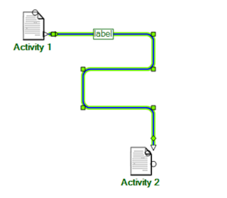
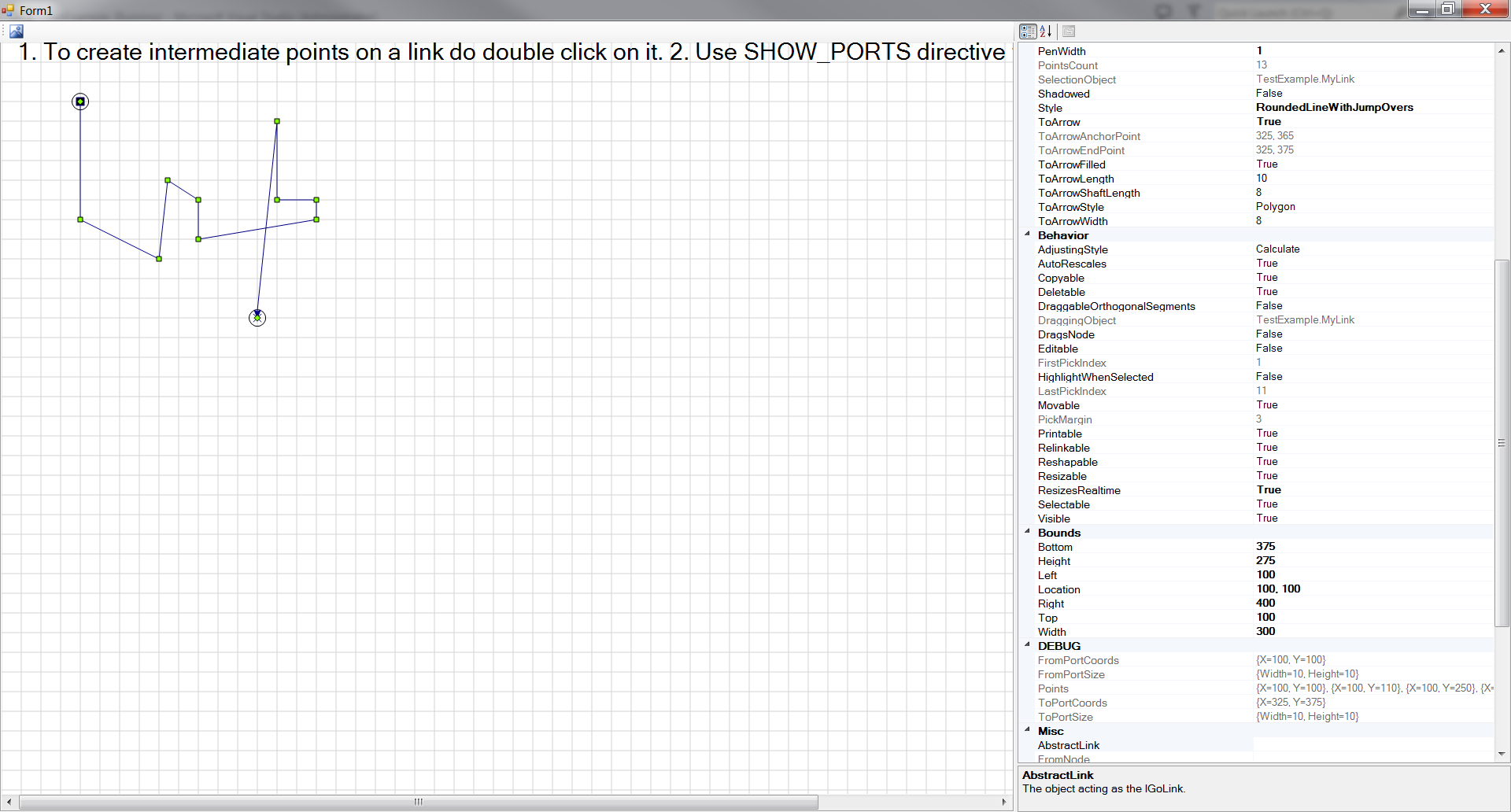
I’ve prepared a simple example to illustrate my questions. To simplify the example I didn’t include objects that must be connected with connectors, there are only links (connectors) which can be connected with each other by relinking.
To be connected, the links have ports at the ends. You can drag one of a connector end to
another connector end to connect them. (To show ports, define conditional compilation symbol SHOW_PORTS for the whole project or only just for MyLink.cs).
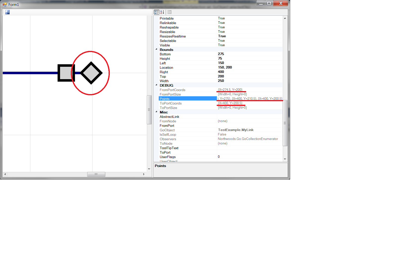
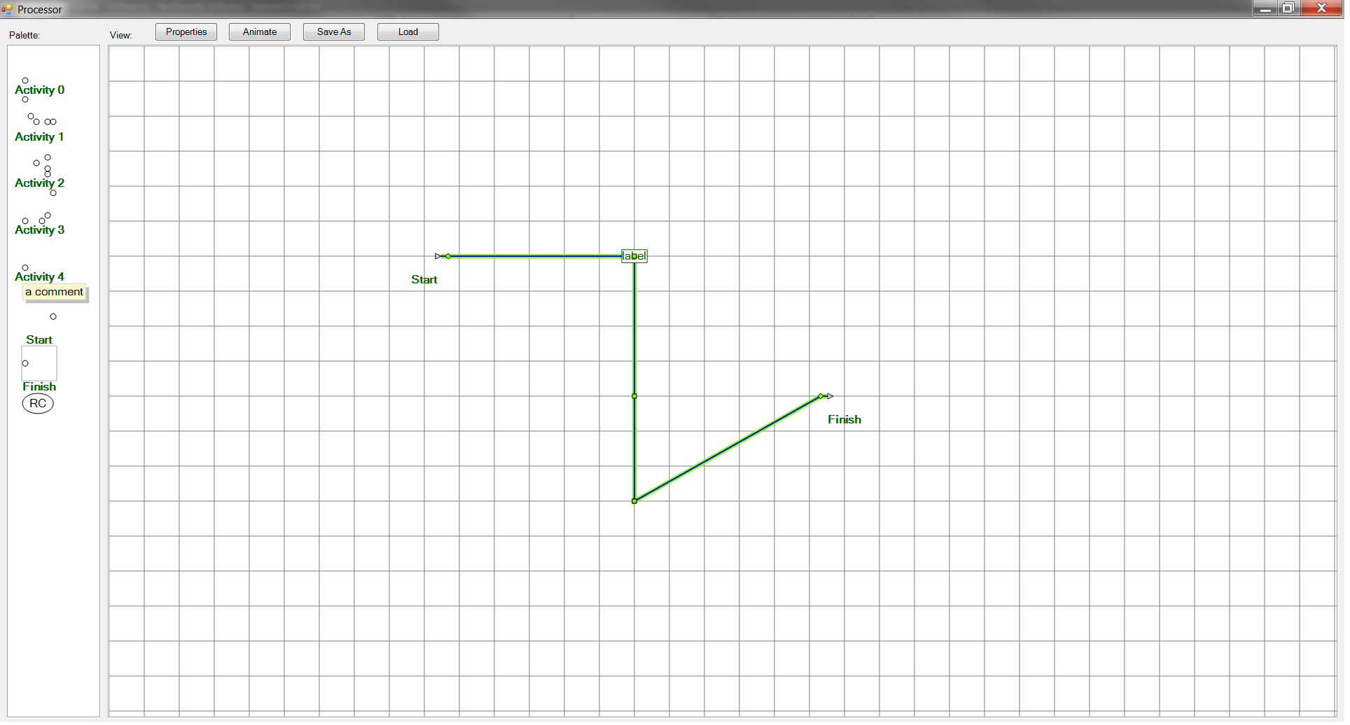
Why do the ends of MyLink have offsets? Look at the pic1.png. I expect the first and last
connector point coords are aligned by grid, but they are not. There is offset of 0.5. Ports have no size. Because of the offset I have a bit curved lines that connect objects and it looks not very good.
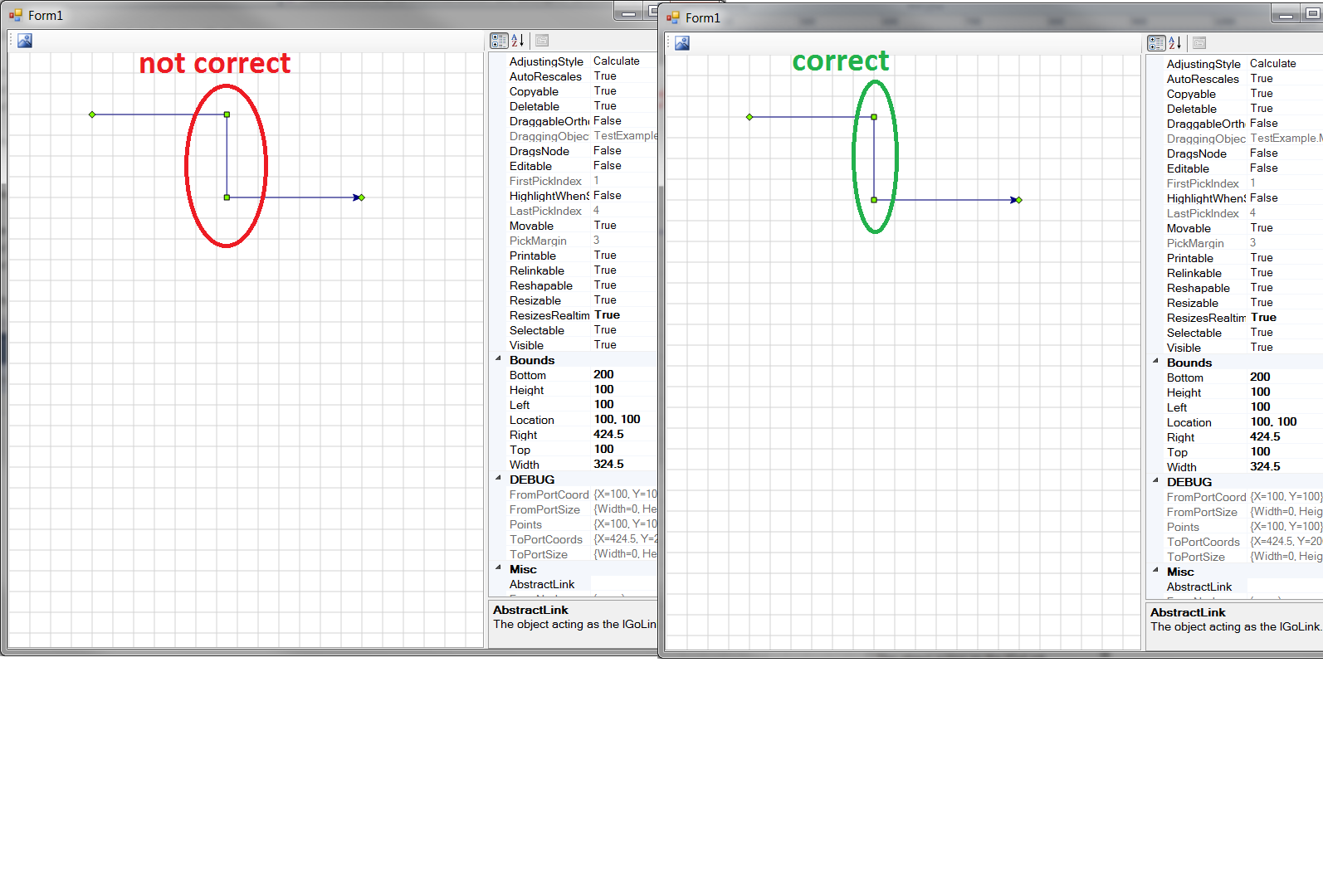
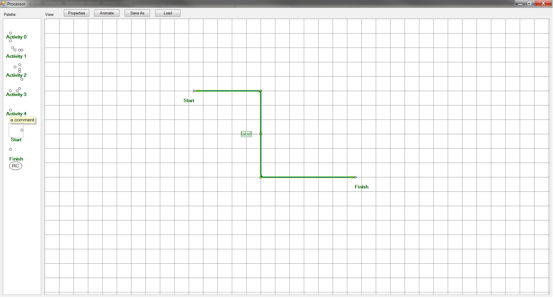
How can I achieve every connector (not only its ends) point to be aligned by grid? I need it when a connector is moving or relinking.
This issue illustrated by pic2.png
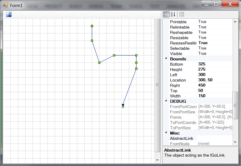
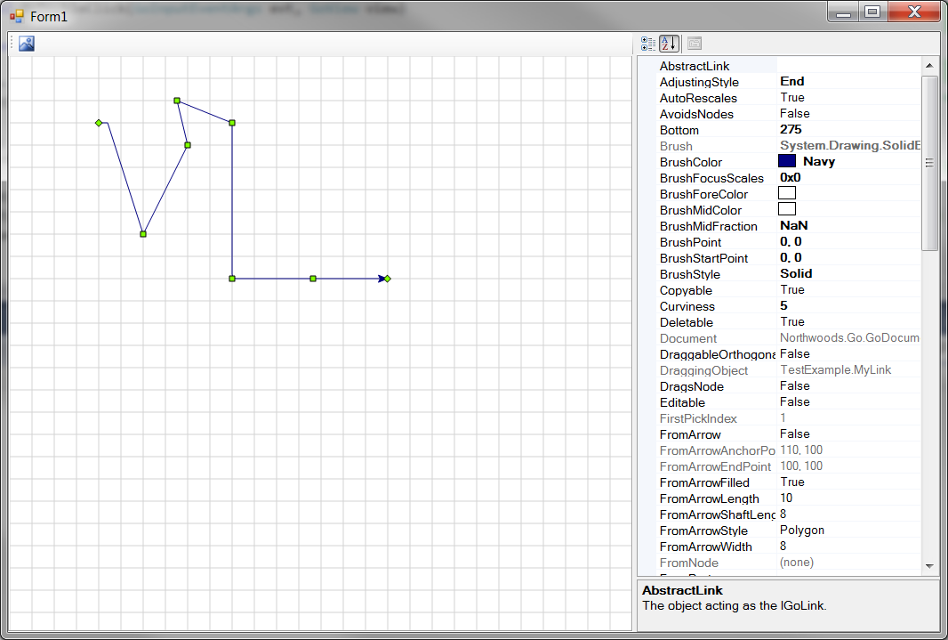
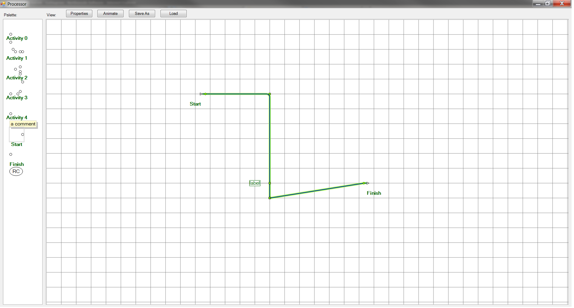
When I move any intermediate connector point, sometimes I have situation when a link segments are not orthogonal to each other (pic3.png). How can I retain orthogonality moving intermediate connector points?
Links draw their first segment in the “From” or “To” direction, and the length of that first segment is defined by GoPort.EndSegmentLength. You can set that to zero.
GoLink routing doesn’t know about grids. Probably the simplest thing to do here is override GoLink.CalculateRoute, call the base method and then “fix up” (i.e. snap) the midpoints to the grid.
ok… a weak first try here:
[Serializable]
public class GoSnapLink : GoLink
{
public override void CalculateRoute()
{
  base.CalculateRoute();

  for (int i = 2; i < this.PointsCount-2; i++)
  {
    PointF pt = this.GetPoint(i);
    float grid = 35.0f;
    float mod = pt.X % grid;
    if (mod < grid/2)
    {
       pt = new PointF(pt.X - mod, pt.Y);
    }
    else {
      pt = new PointF(pt.X - mod + grid, pt.Y);
    }
    this.SetPoint(i, pt);
  }
}
}
note I’m only handling adjusting the X of the vertical segment to be aligned. And the link is aware of the
grid size, because the link doesn’t have easy access to the GoView. (So I cheated.)
so… it would have to be a lot smarter than this, but this is a start. You might have to add points to get the horizontal links aligned if your ports aren’t aligned with the grid.
(this also doesn’t work if you resize (drag) bits of the link.)
Is that a GoLink or a GoStroke? GoLink should handle orthognal resize. See the Processor sample, it lets you add new points to the orthognal link.
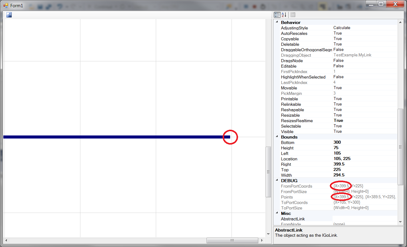
Yes, I know about the GoPort.EndSegmentLength property, but it is not that I need. I meant the first and last connector points are not aligned by grid. Watch at the picture bellow:
You can see, that there is the first point has coords X=399.5, Y=225. My question is - Why do the X value of the first point has strange value 399.5? I expect it should be equal to 400. Because of this little offset I have a bit curved lines on a view. How can I avoid this issue?
By the way, if I set the GoPort.EndSegmentLength to zero, the arrow at the end will desapear. I want the arrows to be visible. Is there any way to get rid of the segments at the ends of GoLink and having the arrows visible?
I have worked around this problem using similar approach, but I passed GoView.SnapPoint method as a delegate to GoLink and used it to align intermediate points by grid. I thought may be there is something out of box to solve the problem: private Func<PointF, GoObject, PointF> _snapPointMethod;
     public override void CalculateStroke()
     {
         base.CalculateStroke();

         if (_snapPointMethod != null)
         {
             for (int i = 2; i < this.PointsCount - 2; i++)
             {
                 PointF pt = _snapPointMethod(this.GetPoint(i), this);
                 this.SetPoint(i, pt);
             }
         }
     }
It is GoLink of course. I forgot to mention, that when we add an extra point on a link (in my example you can add a point with double click on it), I set GoLink.AdjustingStyle = GoLinkAdjustingStyle.End. It is necessary to not lose added points when a user relinking a link. If I don’t do that (GoLink.AdjustingStyle = GoLinkAdjustingStyle.Calculate), each added point will be removed after next CalculateStroke call.
My problem is to give a feature to users to add extra points, retain ones after relinking or other operations, and the most important aspect is that a link must be always orthogonal and its points must be aligned by a grid.
Although a link has its Orthogonal property set to true, when I move its intermediate points, I can get not orthogonal link like at the picture below:
I’ve watched at the example (Processor sample). It’s exactly that behavior I need! Maybe I don’t understand something, but it seems the behavior I’ve described before is accessible out of box? But then why I can move intermediate points in not orthogonal way? Maybe I’ve not set some property properly, or do something wrong… Could you reproduce that incorrect behavior and point me out where I’m mistaken.
I’ve created the GoBasicNode on each end of the GoLink and set FromPort and EndPort to those nodes Port property.
You can see the result in my attached example:
Did I do exactly that you had meant in your answer?
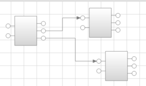
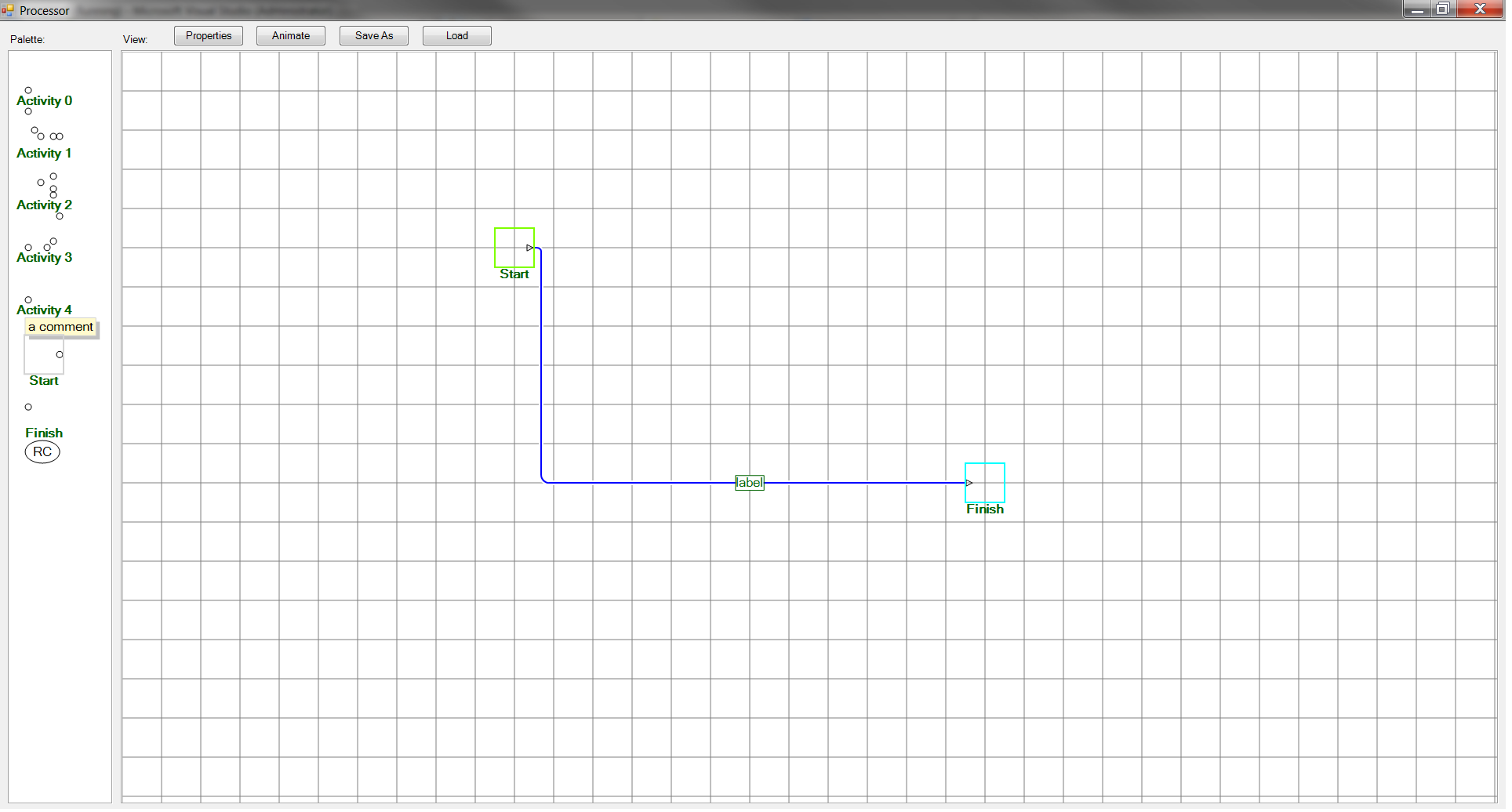
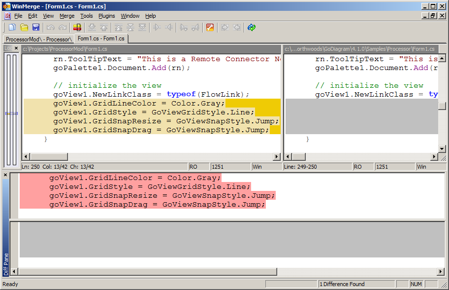
I discovered a bug in you product. I had thought that a bug somewhere in my code, but it isn’t. I downloaded the latest version of GoDiagram (5.2.0.4) and used example Processor as a starting point. The bug consist of the foolowing (look at the picture bellow)
I did it because It’s easier to reproduce the bug when we have lines aligned by grid. When we have no grid snapping to reproduce the bug is very difficult (but possible).
I added two objects at the GoView (Start and Finish)